Cross current control for power converter systems and integrated magnetic choke assembly

Inactive Publication Date: 2005-07-12
GENERAL ELECTRIC CO
View PDF9 Cites 69 Cited by
  • Summary
  • Abstract
  • Description
  • Claims
  • Application Information

AI Technical Summary

Benefits of technology

[0008]Briefly, in accordance with one embodiment of the present invention, a cross current control system for multiple, parallel-coupled power converters comprises common mode chokes, local cross current detectors, local cross current feedback controllers and local converter controllers. Each of the common mode chokes is coupled to a respective power converter. Each local cross current detector is configured for obtaining common mode cross currents from a respective output line of a respective power converter. Each of the local cross

Problems solved by technology

Common mode current that circulates among the paralleled multiple converters or within paralleled converter systems that does not contribute to the output to the load is typically referred to as “cross current.” Both synchronous and interleaved gating control embodiments typically result in undesirable cross current with the cross current being more severe in interleaved embodiments.
In ideal conditions synchronous gating does not lead to cross current, but in actual circuits usin

Method used


Image

  • Cross current control for power converter systems and integrated magnetic choke assembly
  • Cross current control for power converter systems and integrated magnetic choke assembly
  • Cross current control for power converter systems and integrated magnetic choke assembly

Examples


Embodiment Construction

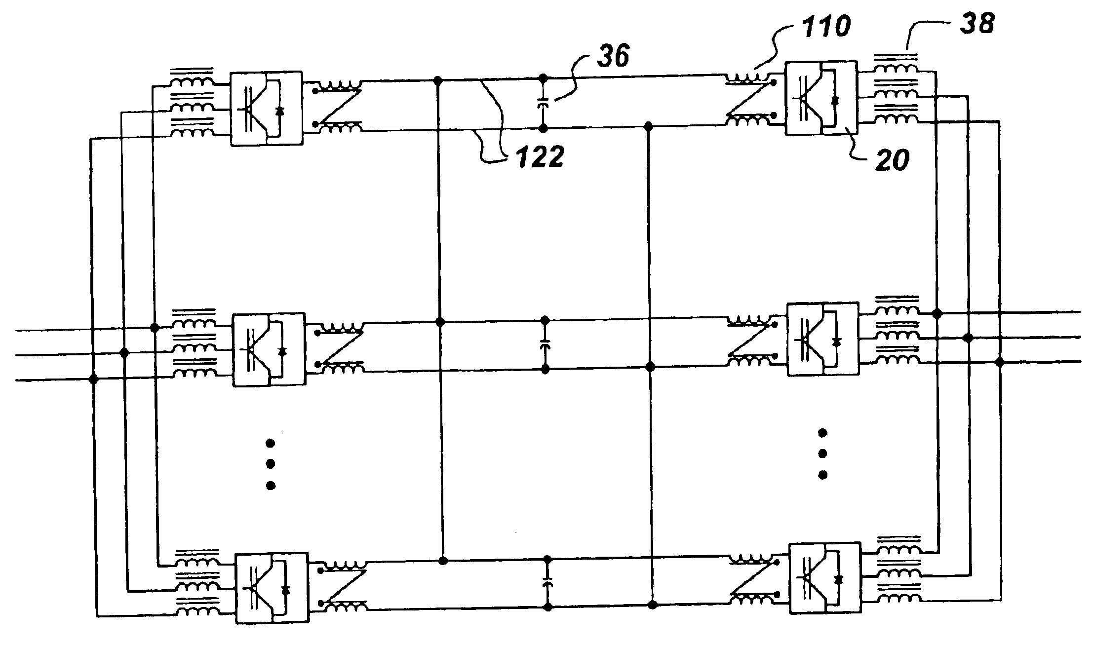
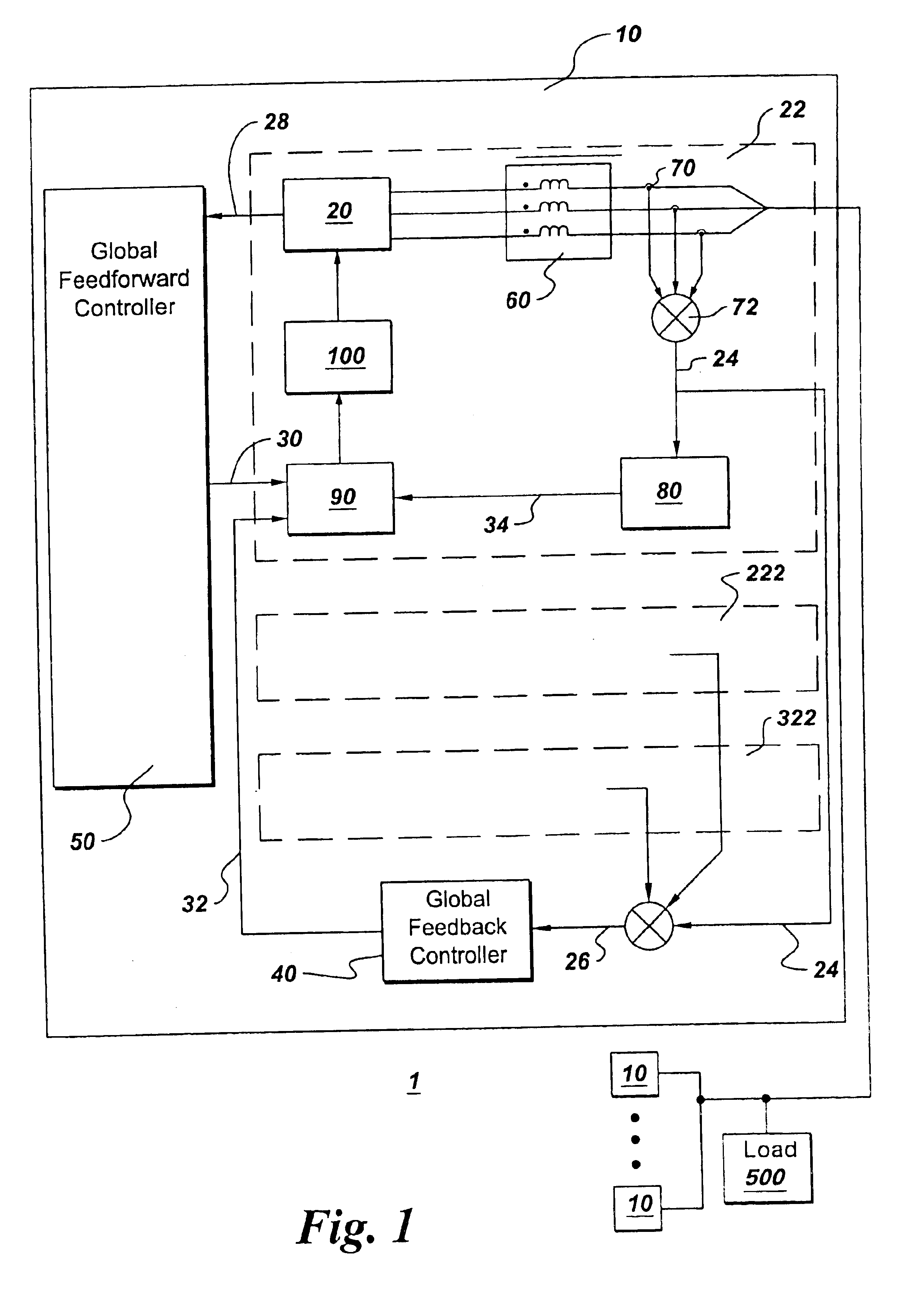
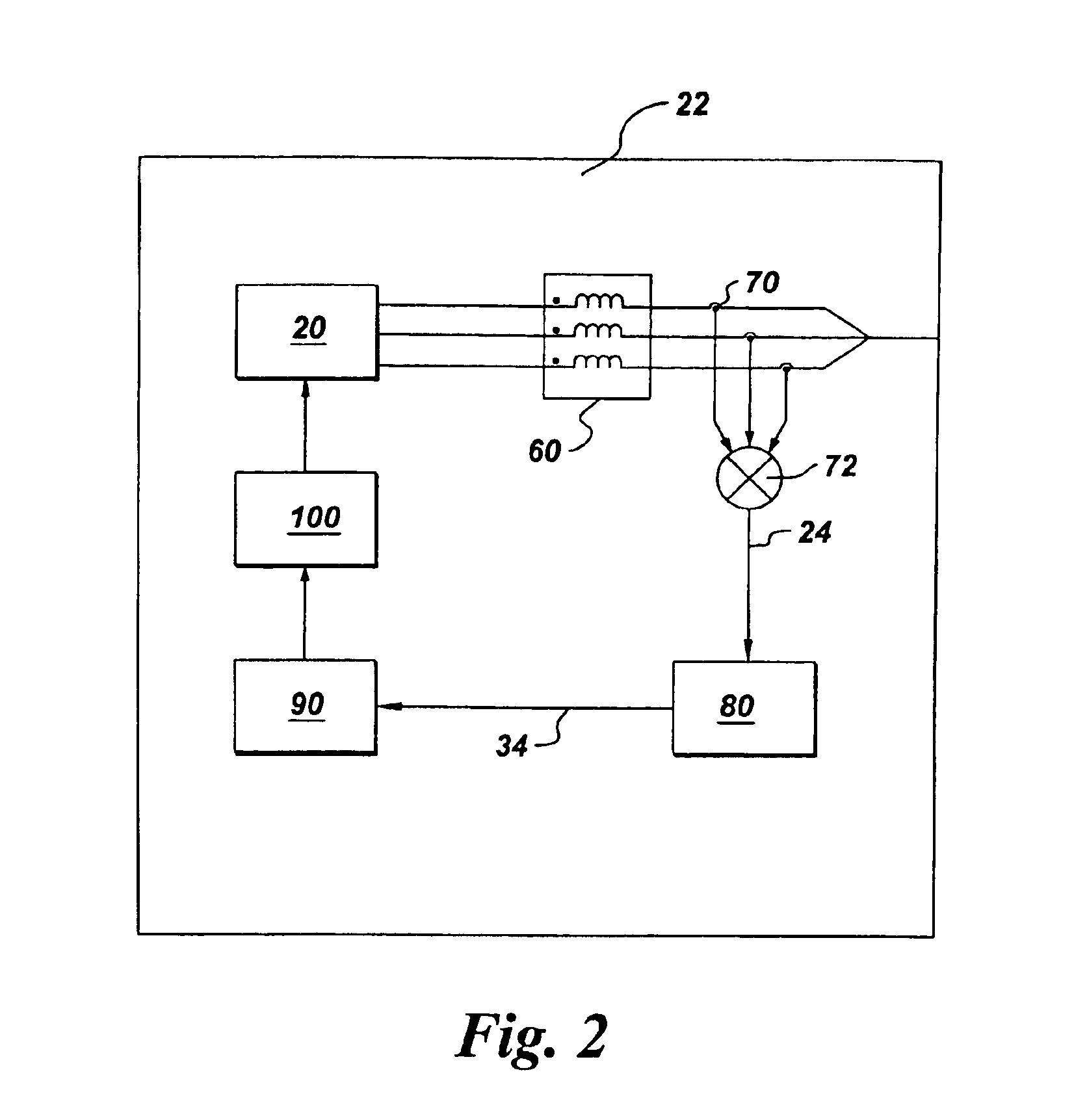
[0028]One embodiment of the present invention is a cross current control system 1 comprising a multi-converter system 10 (or multiple multi-converter systems 10), as illustrated in FIG. 1, to limit the cross current among multiple, parallel, power converters 20, operating in a coordinated fashion without an isolation transformer to drive the load 500. The cross current control system comprises at least two power converters and their respective controls which are shown as individual power converter systems 22, 222, and 322 for purposes of example and each comprise a common mode choke 60, local cross current detectors 70, a local cross current feedback controller 80 and a local converter controller 90, and one or more converters 20.

[0029]The common mode choke is particularly useful for reducing the cross current at the switching frequency level caused by asynchronous switching patterns (created by interleaved control embodiments or imperfect synchronous control embodiments) applied to...


PUM


Abstract

A cross current control system for multiple, parallel-coupled power converters includes common mode chokes, local cross current feedback controllers, and local converter controllers. Each common mode choke is coupled to a respective power converter. Each local cross current feedback controller is configured for receiving common mode cross currents from a respective local cross current detector, calculating a resultant cross current, and generating a local feedback control signal. Each local converter controller is configured for using a respective local feedback control signal to drive the respective power converter in accordance with a coordinated switching pattern. An integral choke assembly includes a common mode choke and a differential mode choke with common and differential mode choke cores configured with at least one magnetic flux path being shared by magnetic flux generated by common mode coils and differential mode coils.

Description

[0001]This application is a Divisional of application Ser. No. 10 / 064,547, filed Jul. 25, 2002, now issued as U.S. Pat. No. 6,751,106, which is hereby incorporated by reference in its entirety.BACKGROUND OF INVENTION[0002]Paralleling multiple power converters is a common practice in the telecom and UPS (uninterruptible power supply) industries to increase overall system power capacities and to enhance system reliabilities by building redundancy. Typical examples of such power converters are single phase or three phase converters comprising inverters, rectifiers and DC / DC converters. Typically all the parallel power converters are gated synchronously and are tied together through isolation transformers to limit the cross current. Synchronous gating implies that the gate controls for the parallel converters are perfectly aligned.[0003]Another way to operate the parallel power converters is through interleaved gating. Interleaved gating means that the switching patterns of the parallel...

Claims


Application Information

Patent Timeline
IPC IPC(8): H02M5/00H02M7/217H02M7/48H02M5/45H02M7/493
CPCH02M5/45H02M7/217H02M7/493H01F37/00H02M1/0043
Inventor ZHANG, RICHARD S.LYONS, JAMES PATRICKGARCES, LUIS JOSEYUAN, XIAOMING
Owner GENERAL ELECTRIC CO
Why Eureka
Try Eureka