
Radio frequency device for receiving TV signals and GPS satellite signals and performing positioning

a radio frequency device and satellite signal technology, applied in the field of position determination and data reception, can solve the problems of limited gps effect, marginal usefulness or no usefulness of signals, and relatively weak received signal strength

Inactive Publication Date: 2005-07-12
TRUE POSITION INC
View PDF3 Cites 95 Cited by
  • Summary
  • Abstract
  • Description
  • Claims
  • Application Information

AI Technical Summary

Benefits of technology

[0021]The details of one or more implementations are set forth in the accompanying drawings and the des

Problems solved by technology

However in some situations, the effectiveness of GPS is limited because the GPS signals are transmitted at relatively low power levels (less than 100 watts) and over great distances, the received signal strength is relatively weak (on the order of −160 dBW as received by an omni-directional antenna).
Thus the signal is marginally useful or not useful at all in the presence of line-of-sight blockage or while the receiver is inside a building.
However, the technique described the use of the horizontal and vertical synchronization pulses which were intended only for relatively crude synchronization of the TV set sweep circuitry, and thus will limit the level of positioning accuracy or reliability of the disclosed location technology.

Method used


Image

  • Radio frequency device for receiving TV signals and GPS satellite signals and performing positioning
  • Radio frequency device for receiving TV signals and GPS satellite signals and performing positioning
  • Radio frequency device for receiving TV signals and GPS satellite signals and performing positioning

Examples


Embodiment Construction

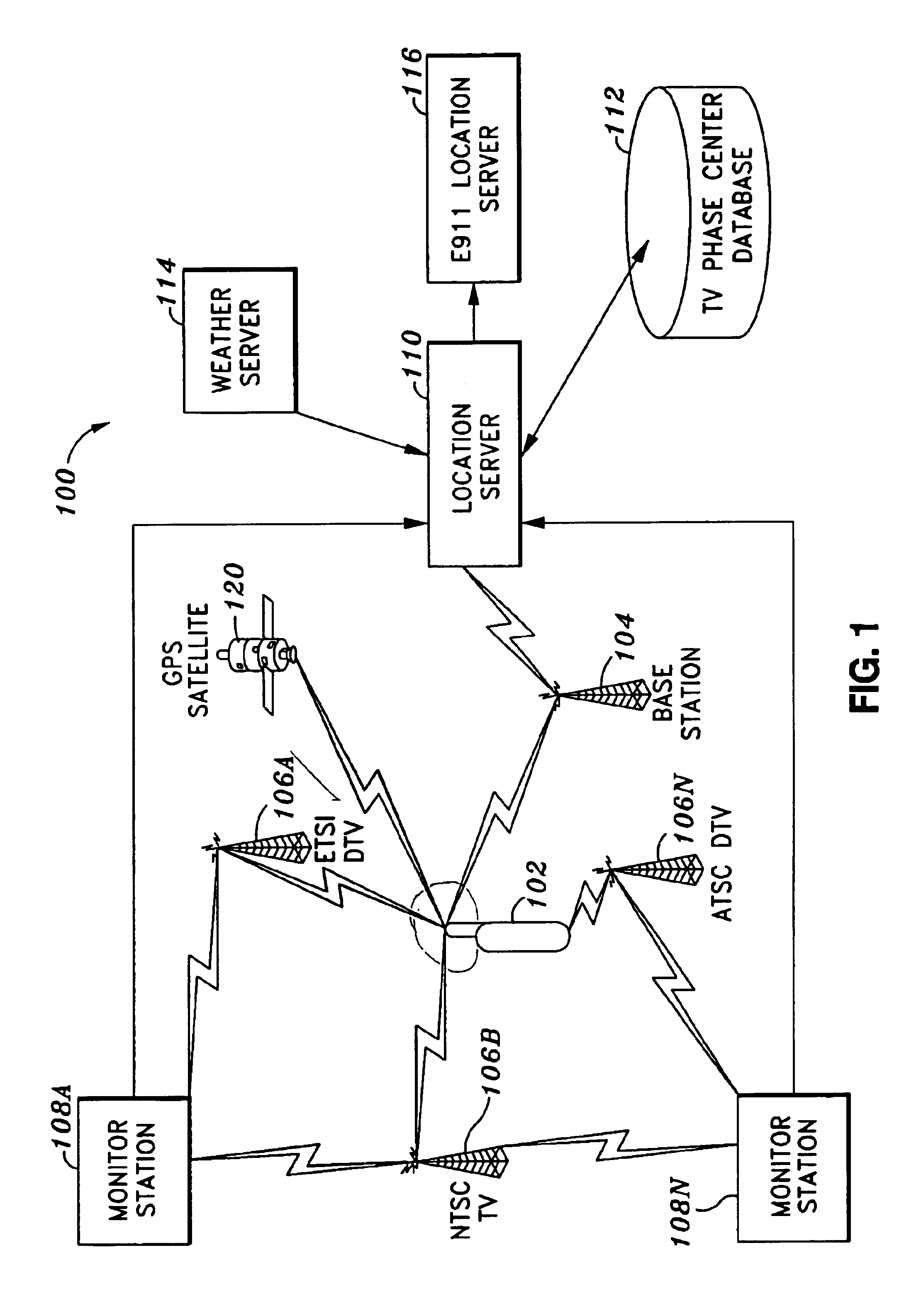
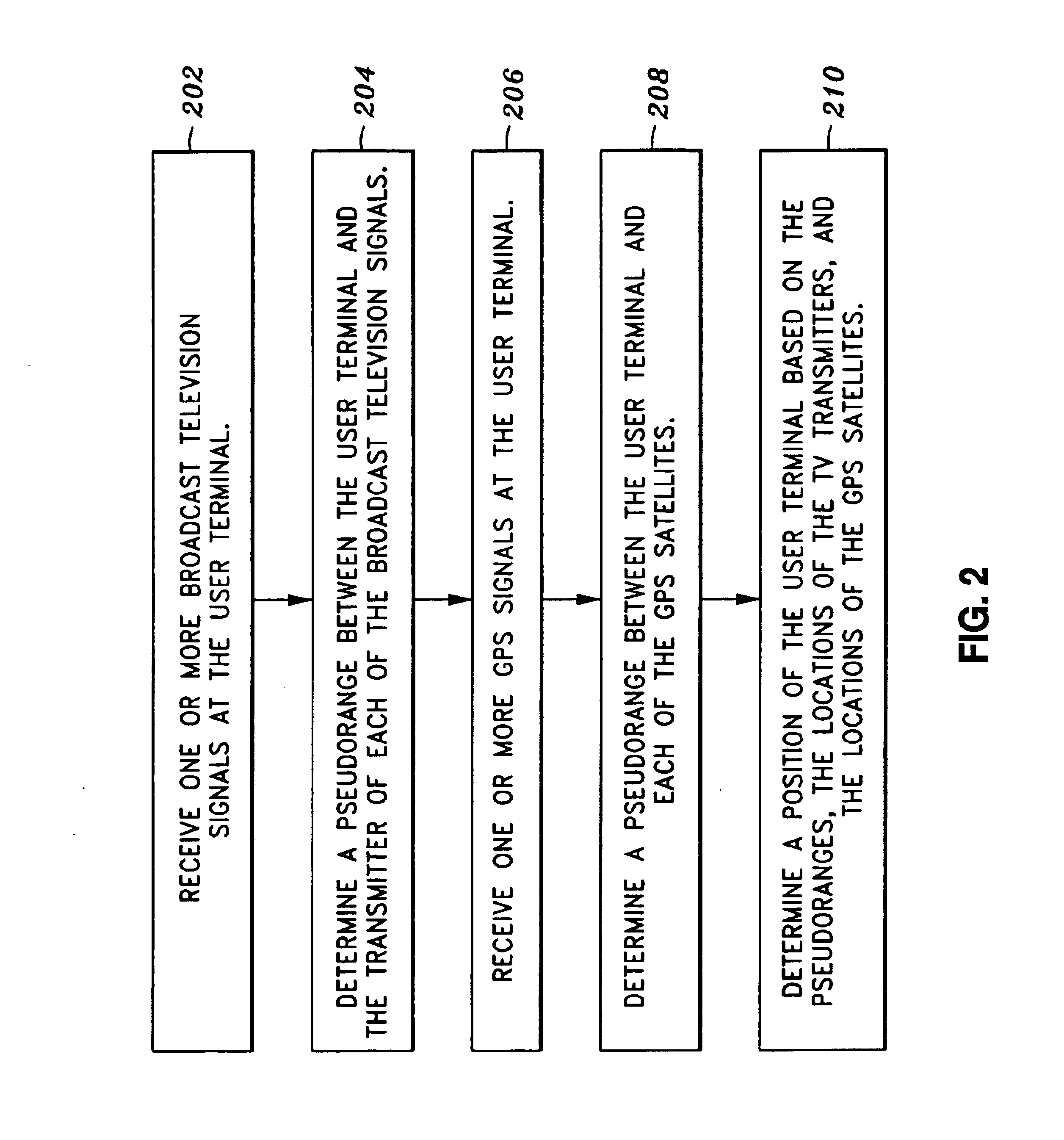
[0038]FIG. 1 depicts an implementation of the present invention including a user terminal 102 that communicates over an air link with a base station 104. As described in FIG. 2, a method for position determination comprises receiving at the user terminal a first set of broadcast television signals from television signal transmitters 202; determining a first set of pseudo-ranges between the user terminal and the television signal transmitters based on a known component of the broadcast television signal 204; receiving at the user terminal a second set of global positioning signals from a set of global positioning satellites 206; determining a second set of pseudo-range between the user terminal and the global positioning satellites based on the global positioning signals 208; and determining a position of the user terminal based on the first and second set of pseudo-ranges, the locations of the set of television signal transmitters, and the locations of the set of global positioning ...


PUM


Abstract

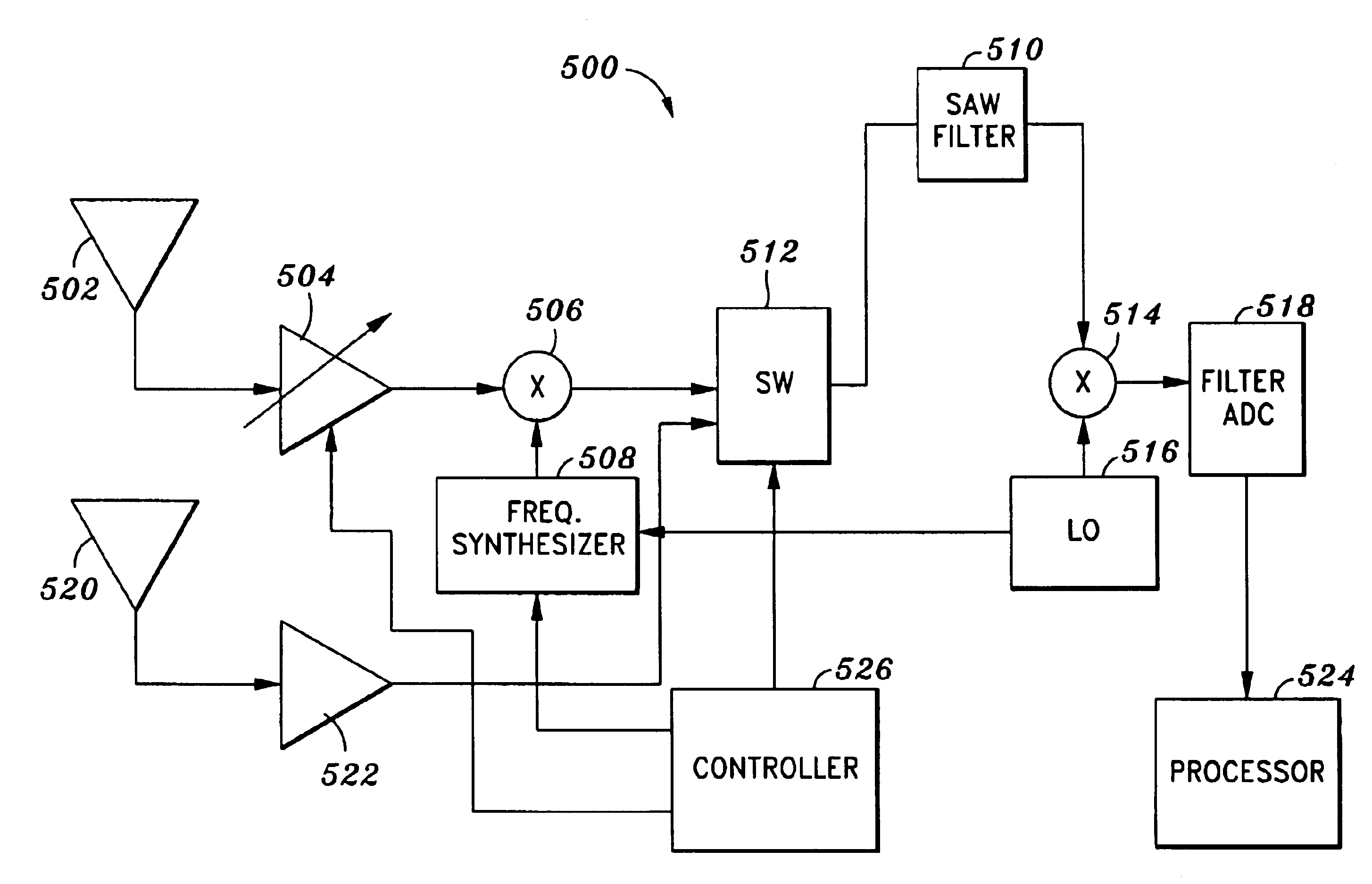
An apparatus and method for determining the position of a user terminal comprise an antenna subsystem which is able to receive signals of GPS and TV, a receiver front end which converts the frequency of the incident signals and filters out unwanted signals so that the desired signals can be sampled, a digital processing component which accommodates the imperfections of the front end and converts the measured signals into a position information. The apparatus is capable of receiving at the user terminal, broadcast television signals from television signal transmitters; determining a first set of pseudo-ranges between the user terminal and the television signal transmitters based on a known component of the broadcast television signals; receiving at the user terminal global positioning signals from a global positioning satellites; determining a second set of pseudo-ranges between the user terminal and the global positioning satellites based on the global positioning signals; and determining a position of the user terminal based on the first and second sets of pseudo-ranges, locations of the television signal transmitters, and locations of the global positioning satellites.

Description

RELATED APPLICATIONS[0001]This application claims the benefit of U.S. Provisional Patent Application Ser. No. 60 / 361,762, “DTV Position Location Augmented by GPS,” by James J. Spilker, filed Mar. 4, 2002; U.S. Provisional Patent Application Ser. No. 60 / 341,922, “An Inexpensive Hardware and Signal Processing Technique for Tracking Television Signals in a Mobile Handheld Device,” by Matthew Rabinowitz, filed on Dec. 18, 2001; U.S. Provisional Patent Application Ser. No. 60 / 353,440, “DTV Position Location Augmented by GPS,” by James J. Spilker, filed Feb. 1, 2002; U.S. Provisional Patent Application Ser. No. 60 / 332,504 “DTV Augmented GPS for Robust Aircraft Navigation,” by James J. Spilker, filed Nov. 13, 2001, the disclosures thereof are incorporated by reference herein in their entirety.[0002]This application is related to U.S. Non-provisional Patent Application Ser. No. 10 / 003,128, “Robust Data Transmission Using Broadcast Digital Television Signals,” by James K. Omura, James J. Spi...

Claims


Application Information

Patent Timeline
IPC IPC(8): G01S5/02G01S5/00G01S5/14H03L7/087H03L7/08G01S19/46
CPCG01S5/0036G01S5/0221G01S19/31G01S19/36G01S19/46G01S5/0215G01S19/25H03J2200/13H03L7/087G01S5/0218
Inventor RABINOWITZ, MATTHEWSPILKER, JR., JAMES J.
Owner TRUE POSITION INC
Learn More