Optical transmission system for compensating for transmission loss

a transmission system and optical transmission technology, applied in the field of optical transmission systems, can solve the problems of changing errors can be generated in the data recovered by the optical receiver of the receiving apparatus, and the transmission efficiency of the optical transmission system can change, so as to achieve uniform transmission efficiency of the optical transmission system

Inactive Publication Date: 2005-07-12
SAMSUNG ELECTRONICS CO LTD
View PDF19 Cites 36 Cited by
  • Summary
  • Abstract
  • Description
  • Claims
  • Application Information

AI Technical Summary

Benefits of technology

[0014]To address the above issues, it is an object of the present invention to provide an optical transmission system for compensating for transmission loss so that the transmission efficiency of an optical transmission system is kept uniform regardless of the characteristics of an optical fiber and a receiving apparatus.

Problems solved by technology

For example, when transmission loss is generated while the optical signal is transmitted through the optical fiber, or received by the receiving apparatus, errors can be generated in the data recovered by the optical receiver of the receiving apparatus.
Also, the transmission efficiency of the optical transmission system can change since the characteristics of the devices used as the optical fiber may not optimally match.
Accordingly, errors can be generated in the data recovered by the optical receiver of the receiving apparatus.
Accordingly, errors can be generated when data is transmitted.
However, the change in transmission efficiency according to the characteristics of the optical fiber and the receiving apparatus is not taken into account.
Accordingly, it is not possible to compensate for errors generated when data is transmitted.
Therefore, when the conventional optical transmission system of the open loop is constituted, restrictions are placed on selection of the devices.
Accordingly, it is expensive to constitute the optical transmission system.

Method used


Image

  • Optical transmission system for compensating for transmission loss
  • Optical transmission system for compensating for transmission loss
  • Optical transmission system for compensating for transmission loss

Examples


Embodiment Construction

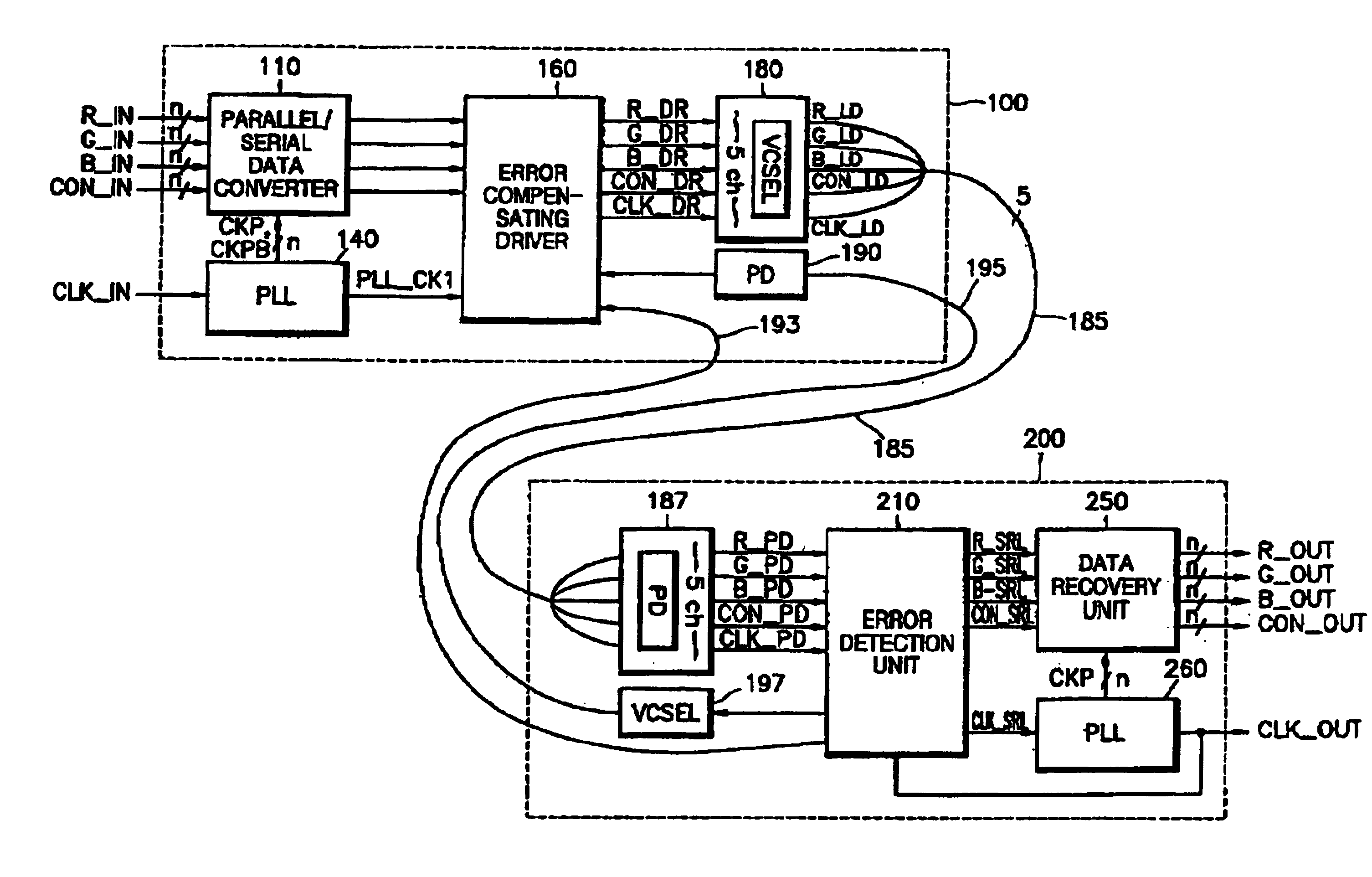
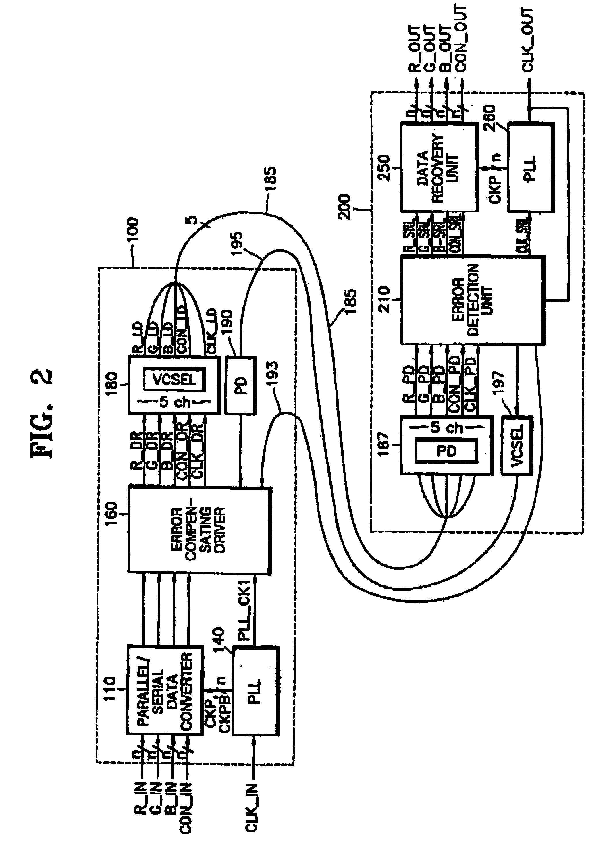
[0039]FIG. 2 is a schematic block diagram showing an optical transmission system for compensating for transmission loss according to an embodiment of the present invention. The optical transmission system includes a transmitting apparatus 100, first and second optical fibers 185 and 195, and a receiving apparatus 200. The second optical fiber 195 can be replaced by an electrical transmission line 193. In the present specification, the optical transmission system using the second optical fiber 195 will be described.

[0040]The transmitting apparatus 100 serializes n-bit channel data items received from an external source in response to a predetermined clock signal CLK. The transmitting apparatus 100 converts the serialized channel data items and predetermined clock signal CLK into optical signals and outputs the optical signals. The transmitting apparatus 100 can change the output power of the respective optical signals output from the transmitting apparatus 100 in response to an error...


PUM


Abstract

An optical transmission system for compensating for transmission loss includes a transmitting apparatus for serializing a plurality of n (n is a natural number)-bit channel data received from the outside in response to a predetermined clock signal, converting the serialized channel data and the predetermined clock signal into a current signal whose magnitude changes corresponding to an error detection signal, and outputting optical signals having optical output power corresponding to the magnitude of the current signal, a first optical fiber for transmitting the optical signals, a receiving apparatus for recovering the n-bit channel data and the predetermined clock signal from the optical signals received through the first optical fiber, detecting transmission loss generated when the optical signals are transmitted and received, optically converting the transmission loss, and outputting the optically converted transmission loss as the error detection signal, and a second optical fiber for transmitting the optical converted error detection signal to the transmitting apparatus. Since the receiving apparatus and the transmitting apparatus forms a closed loop, it is possible to keep optical efficiency uniform, corresponding to the transmission loss transmitted by the receiving apparatus. Also, the parallel/serial data converter is realized by the gate, it is possible to convert data at high speeds of greater than the GHz level and to reduce the size of the circuit. Also, it is possible to reduce power consumption since the non-overlapping clock signals whose frequencies are relatively low are used even when data is converted at high speeds greater than the GHz level.

Description

BACKGROUND OF THE INVENTION[0001]1. Field of the Invention[0002]The present invention relates to an optical transmission system, and more particularly, to an optical transmission system for compensating for transmission loss, an optical signal transmitting / receiving apparatus of the optical transmission system for compensating for transmission loss, and a parallel / serial data converter for transmitting high speed data in the transmitting apparatus.[0003]2. Description of the Related Art[0004]An optical transmission system includes an optical signal transmitting apparatus, an optical fiber, and an optical signal receiving apparatus. The transmitting apparatus converts an electrical signal to be transmitted into an optical signal, using a laser diode. The optical fiber transmits the optical signal converted by the transmitting apparatus to a receiving apparatus. The receiving apparatus receives the optical signal transmitted through the optical fiber at a photo diode and converts the ...

Claims


Application Information

Patent Timeline
Patent Type & Authority Patents(United States)
IPC IPC(8): H03K5/15H04B10/18H04B10/155H04B10/152H03M9/00H04B10/08H03L7/099H03L7/08H04B10/077H04B10/2507H04B10/50H04B10/564H04N7/22
CPCH03K5/1504H03M9/00H04B10/0775H04B10/2507H04B10/504H04B10/564H04N7/22H03L7/0995H04B2210/077H04B2210/074H04B10/25
Inventor KIM, YONG-SUB
Owner SAMSUNG ELECTRONICS CO LTD
Why Eureka
Try Eureka