
Calls identify scenario for control of software objects via property routes

Inactive Publication Date: 2005-07-12
UNILOC 2017 LLC
View PDF7 Cites 60 Cited by
  • Summary
  • Abstract
  • Description
  • Claims
  • Application Information

AI Technical Summary

Benefits of technology

"The invention provides an information processing system that allows for independent execution of multiple routes that do not interfere with each other. The system uses identifiers to conditionally invite a property route based on the source object's property and the application that registered the route. The system can log any sequence of property changes and remove or enable / disable routes based on the system's state, time, available resources, and so on. This independence adds another degree of freedom to using an object-based information processing system."

Problems solved by technology

If the order were reversed, calls would be forwarded to the second object without the first object's property having undergone a change, leading to inconsistencies.

Method used


Image

  • Calls identify scenario for control of software objects via property routes
  • Calls identify scenario for control of software objects via property routes
  • Calls identify scenario for control of software objects via property routes

Examples


Embodiment Construction

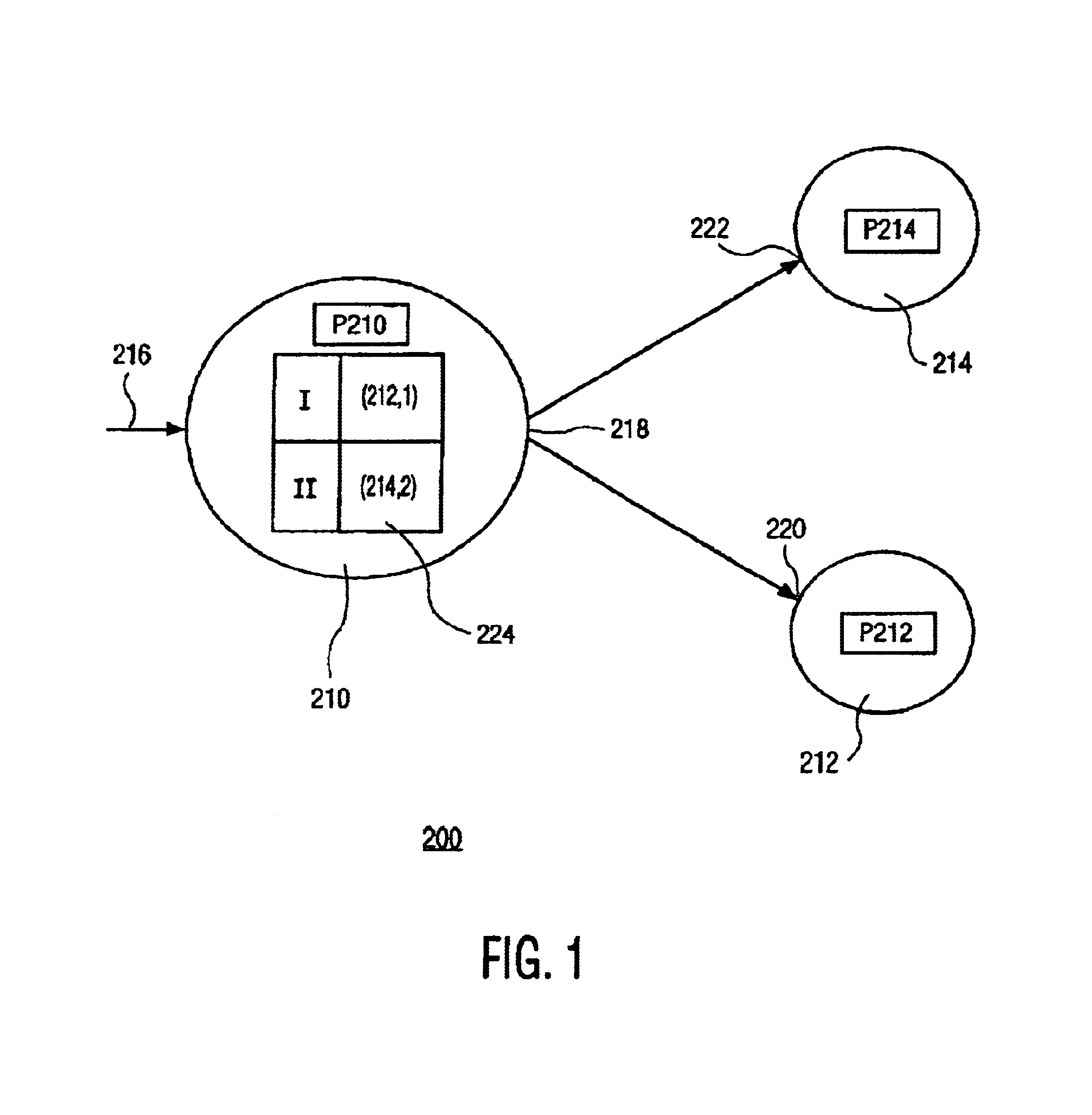
[0016]FIG. 1 is a block diagram 200 illustrating the scenario-controlled routing of property changes, according to the invention, among software objects 210, 212 and 214. Software object 210 has an input 216 an input for receiving an input call, and an output 218 for issuing an output call. Object 212 has an input 220 for receiving an input call. Object 214 has an input 222 for receiving an input call. Object 210 has multiple properties of which only a property P210 is shown in order to not obscure the drawing. Property P210 is changeable through an input call at input 216 that refers to property P210. Objects 212 and 214 have respective properties P212 and P214 that are changeable through proper input calls at inputs 220 and 222, respectively.

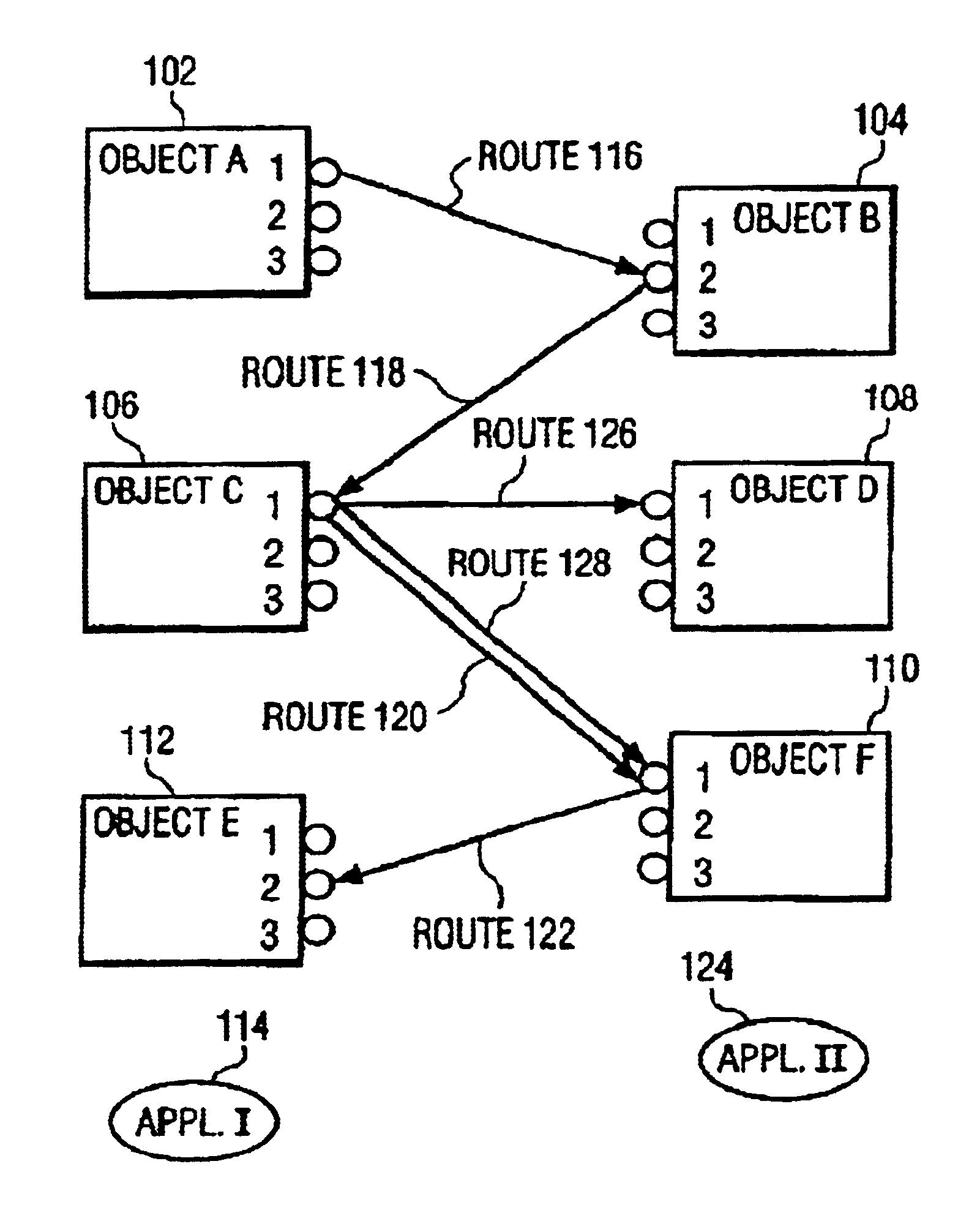
[0017]A first client application (not shown) has registered a first route linking property P210 to property P212 so that a change in property P210 causes object 210 to issue an output call at output 218 to object 212 for changing property P212...


PUM


Abstract

An information processing system has first and second physical components represented by a first and second software objects. Both objects have properties that are changeable through calls to the objects. The system enables registering a property route linking a first property of the first object to a second property of the second object so that a change in the first property causes the second call being issued to the second object upon invoking the property route. The input call to the first object comprises an identifier enabling to conditionally invoke the route. In this manner, routes belonging to different scenarios are being kept independent so that the system operates more reliable that without scenario identifiers.

Description

FIELD OF THE INVENTION[0001]The invention relates to an information processing system and a method, in particular, but not exclusively, for control of consumer electronics equipment in the home or office environment.BACKGROUND ART[0002]Consider a client-server model based on Component Object Model (COM) technology of Microsoft. For more information, see, e.g., the Component Object Model Specification version 0.9 of October 1995 as supplied by Microsoft, herein incorporated by reference. COM is object-oriented. An object has properties that represent control functionalities of an associated electronic device as exposed to a software application. A state change of an object as a consequence of an event from outside is passed on to the software application. The application manipulates the objects by changing or setting their properties. When the application modifies property of an object associated with a certain physical device a command is sent to the associated device.[0003]COM is a...

Claims


Application Information

Patent Timeline
Patent Type & Authority Patents(United States)
IPC IPC(8): G06F9/44H04L12/28H04L12/64G06F9/54H04L12/40
CPCG06F9/4428H04L12/2805H04L12/2827H04L12/40117H04L12/2821H04L2012/2849G06F9/4488G06F9/449
Inventor SHTEYN, YEVGENIY EUGENE
Owner UNILOC 2017 LLC
Learn More