Bi-propellant injector with flame-holding zone igniter

a technology of injector and igniter, which is applied in the direction of machines/engines, explosives, lighting and heating apparatus, etc., can solve the problems of high injector velocities, exceeding flame propagation speeds, and difficult control

Active Publication Date: 2005-07-19
THE BOEING CO +1
View PDF78 Cites 31 Cited by
  • Summary
  • Abstract
  • Description
  • Claims
  • Application Information

AI Technical Summary

Benefits of technology

[0016]Another advantage of the present invention is that it is versatile since it provides multiple bi-propellant injector configurations to satisfy various operating applications and conditions.
[0017]Furthermore, the present invention provides smooth reliable ignition of various propellant combinations, th...

Problems solved by technology

In addition to the existing high and low mixture ratios (outside of flammability limits), which are difficult to propagate combustion therethrough, propellant injection velocities are typically high near the injector face, sometimes exceeding flame propagation speeds.
The combination of high and low mixture ratios and high propellant velocities, results in difficult to control and unreliable ignition propagation.
These temperature spikes and pops over time cause degradation of turbine components due to the higher operating temperatures and thermal stresses.
Generally, when mixture ratios are increased sufficie...

Method used


Image

  • Bi-propellant injector with flame-holding zone igniter
  • Bi-propellant injector with flame-holding zone igniter
  • Bi-propellant injector with flame-holding zone igniter

Examples


Embodiment Construction

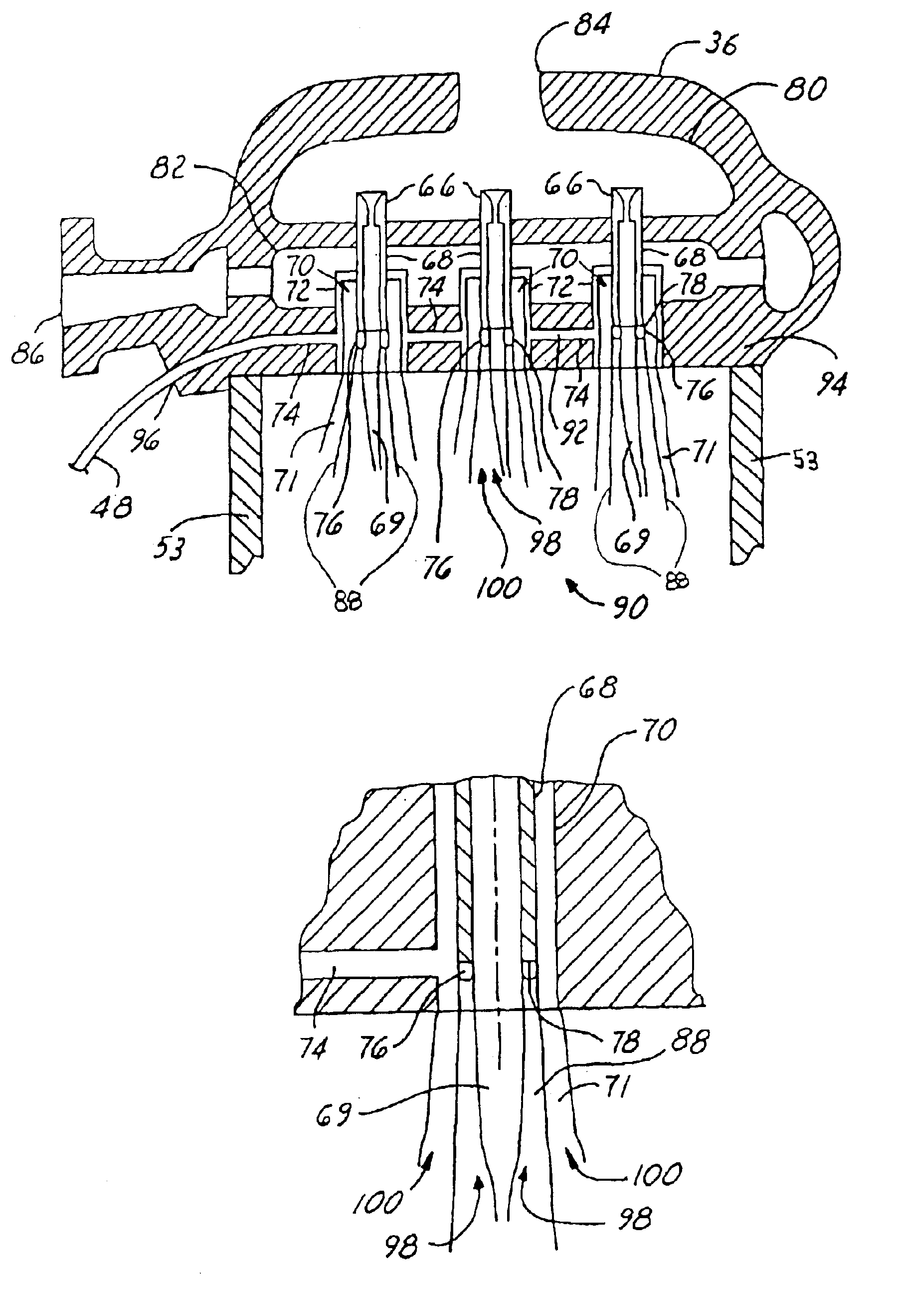
[0032]In each of the following figures, the same reference numerals are used to refer to the same components. While the present invention is described with respect to systems for igniting an oxidizer-fuel mixture within a flame-holding zone of a bi-propellant coaxial injector as well as a method of operating a bi-propellant coaxial injector system, the present invention may be adapted for various applications. The present invention may be applied to gas turbine combustion systems or to other engines having propellant / fuel injectors with a flame-holding zone or similar characteristics therein.

[0033]In the following description, various operating parameters and components are described for one constructed embodiment. These specific parameters and components are included as examples and are not meant to be limiting.

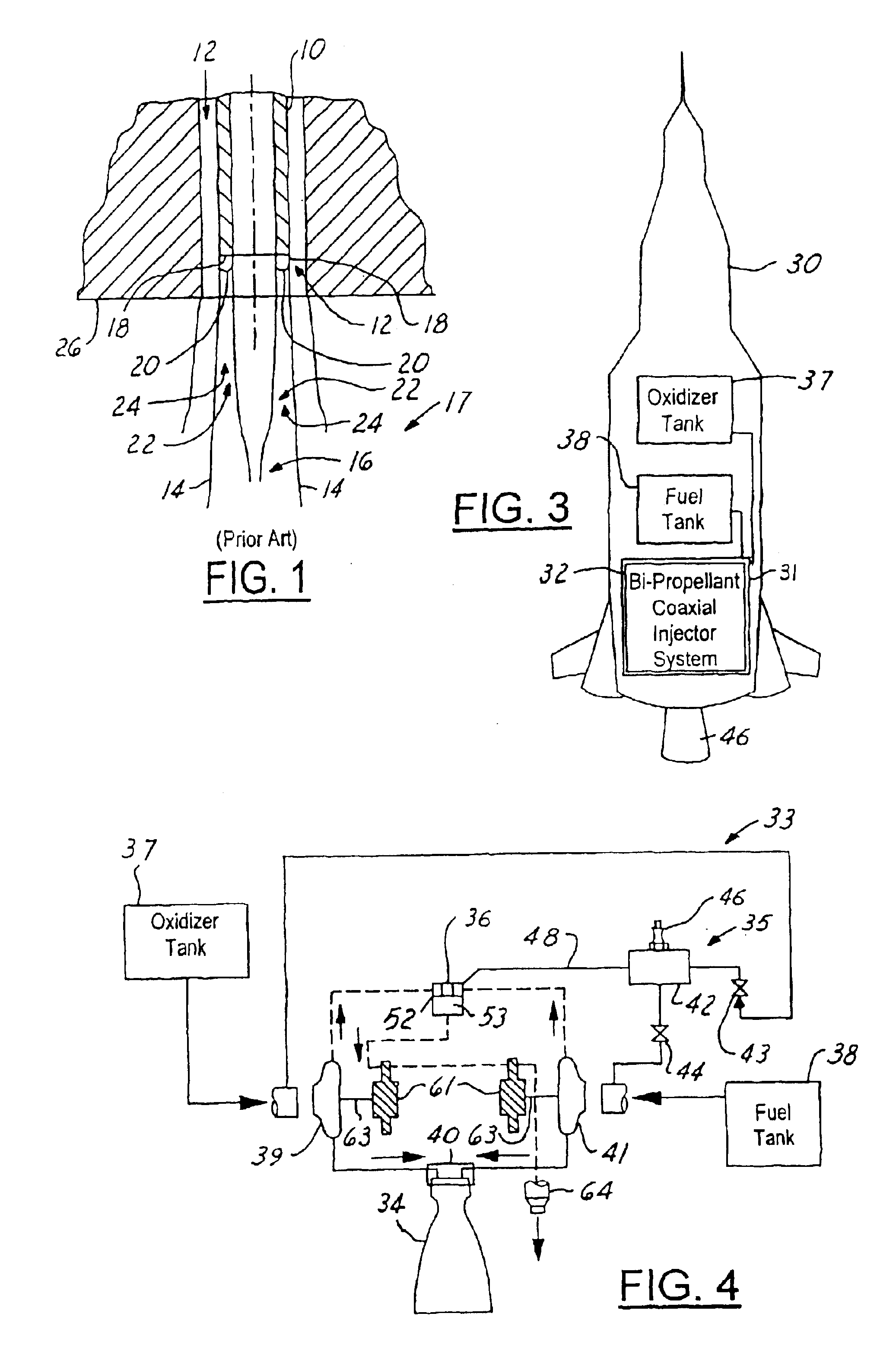
[0034]The present invention is directed towards a bi-propellant injector having a first injector element injecting a first propellant and a second injector element injecti...


PUM


Abstract

A bi-propellant injector (66) includes a first injector element (68) and a second injector element (70) injecting a first propellant (69) and a second propellant (71), respectively, into a combustion chamber (53). A flame-holding zone igniter (74) is adjacent to and ignites recirculation of at least a portion of the first propellant (69) and at least a portion of the second propellant (71) within a flame-holding zone (76).

Description

TECHNICAL FIELD[0001]The present invention relates generally to rocket engine injectors and ignition systems, and more particularly, to systems for igniting a propellant mixture within a favorable ignition zone of a bi-propellant injector as well as a method of operating a bi-propellant injector system.BACKGROUND OF THE INVENTION[0002]Liquid propellant rocket engines, commonly utilize bi-propellant coaxial injection elements or the like for injection and combustion of oxidizer and fuel in a combustion chamber. Hundreds of injector elements may exist in supplying propellant to a single combustion chamber.[0003]Referring now to FIG. 1, a close-up cross-sectional view of a traditional coaxial injector element with a flame-holding zone is shown. Coaxial elements typically inject a first propellant through a central post 10 and a second propellant through a surrounding annulus 12. The propellants being oxidizer and fuel. Shear flow created at a boundary 14 between the fuel and the oxidiz...

Claims


Application Information

Patent Timeline
IPC IPC(8): C06D5/00F02K5/00F02K9/00F02K9/44F23R5/00
CPCF02K9/42F02K9/48F02K9/95
Inventor FISHER, STEVEN C.
Owner THE BOEING CO
Why Eureka
Try Eureka