Method of measuring fluid phases in a reservoir

a technology of fluid phase and reservoir, which is applied in the direction of liquid/fluent solid measurement, instruments, machines/engines, etc., can solve the problems of increasing the time required to install the floating arm mechanism, affecting the operation of the same motor vehicle, and affecting the operation of the same floating arm mechanism

Inactive Publication Date: 2005-07-19
DELPHI TECH INC
View PDF6 Cites 41 Cited by
  • Summary
  • Abstract
  • Description
  • Claims
  • Application Information

AI Technical Summary

Problems solved by technology

That same motor vehicle will not function properly without the proper amount of oil stored in the internal combustion engine allowing it to lubricate and cool itself.
First, the floating arm mechanism requires moving parts inside a liquid-filled container.
This requires increased time to install the floating arm mechanism and seal it and the container or reservoir.
Resistive strips used by the floating arm mechanism are susceptible to contamination and can develop contact problems.
The contamination and contact problems result in erroneous measurements.
Looking forward, the floating arm fluid measuring mechanism will not be able to differentiate between different types of liquids within the same reservoir.
This problem will increase in the automotive environment as different types of fuels will be acc

Method used


Image

  • Method of measuring fluid phases in a reservoir
  • Method of measuring fluid phases in a reservoir
  • Method of measuring fluid phases in a reservoir

Examples


Embodiment Construction

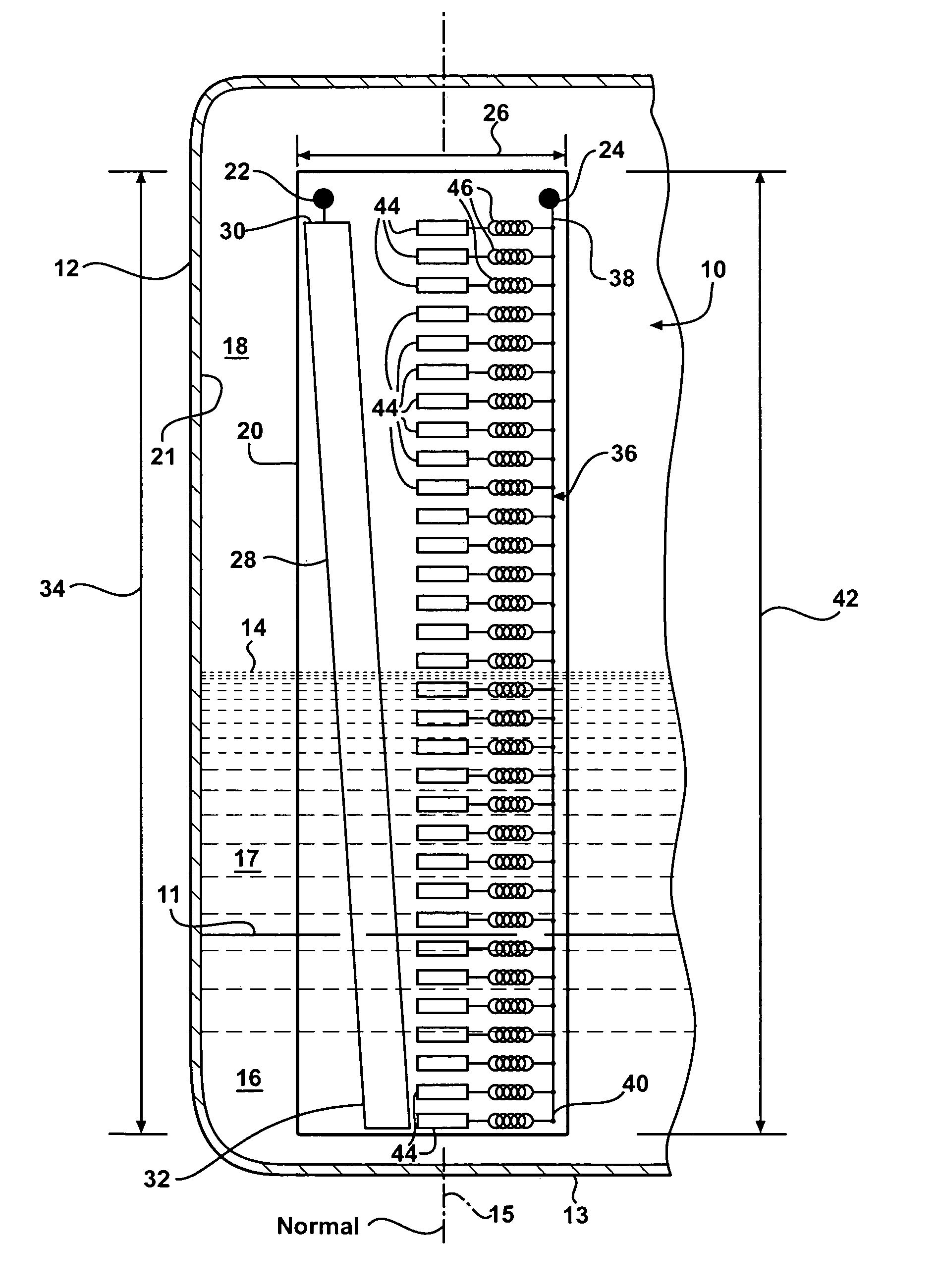
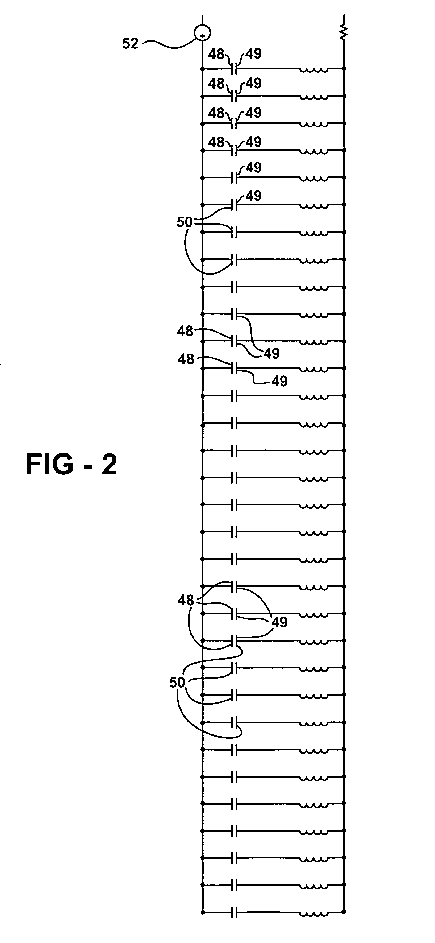
[0017]Referring to FIG. 1, a sensing assembly is generally indicated at 10. The sensing assembly 10 senses liquid levels in a reservoir 12. The sensing assembly 10 creates a sensing signal 54 (shown in FIGS. 3 and 4) to identify levels 11, 14 that liquids 16, 17 are at within the reservoir 12. The sensing assembly 10 is designed such that it is presumed that air 18 fills the portion of the reservoir 12 that the liquids 16, 17 do not. While it is contemplated that the embodiment shown in the Figures illustrates a sensing assembly 10 for a fuel tank 12 of a motor vehicle, it should be appreciated that the reservoir 12 may be any reservoir designed to hold liquids 16, 17 therein and that there may be any number of liquids stored within the reservoir 12.

[0018]The reservoir 12 includes a bottom surface 13 that defines a normal 15 extending up therefrom. In the instance when the bottom surface 13 does not extend through a single plane parallel to the horizon, the normal 15 will be treated...


PUM


Abstract

A method identifies a level of each of a plurality of liquids in a reservoir. The method includes using a sensing assembly having first and second electrodes extending along a side of the reservoir, wherein the first and second electrodes combine to form a plurality of capacitors each having a unique capacitance. The method includes the steps of applying an input AC signal voltage to the first electrode. An output AC signal voltage is then measured across the second electrode. The method continues by locating clusters of frequency variations. The method then associates a level identification for each of the plurality of liquids with each of the clusters of frequency variations.

Description

BACKGROUND ART[0001]1. Field of the Invention[0002]The invention relates to a method for measuring fluid levels in a reservoir. More particularly, the invention relates to a method for measuring fluid levels in a reservoir having multiple fluids being stored therein by analyzing the resonance of the output signal of the fluid level sensing assembly.[0003]2. Description of the Related Art[0004]The storage and delivery of liquids is an important feature of many mechanisms. In an automotive environment, proper delivery of liquids is essential for the functioning and maintenance of a motor vehicle. By way of example, a motor vehicle will not function without fuel, typically liquid gasoline. That same motor vehicle will not function properly without the proper amount of oil stored in the internal combustion engine allowing it to lubricate and cool itself. These are just two fluids in a particular environment that require close observation to make sure its host mechanism, i.e., the motor ...

Claims


Application Information

Patent Timeline
IPC IPC(8): G01F23/00G01F23/26
CPCG01F23/263G01F23/265G01F23/266G01F23/268G01F22/00
Inventor URQUIDI, CARLOS A.SANCHEZ, FRANCISCO J
Owner DELPHI TECH INC
Why Eureka
Try Eureka