Heatsink buffer configuration

a heatsink and buffer technology, applied in the construction details of electrical apparatuses, basic electric elements, lighting and heating apparatus, etc., can solve the problems of affecting the thermal conductivity of the heatsink, and presenting several undesirable design characteristics, so as to improve the thermal conductivity and improve the manufacturing and assembly characteristics. , the effect of improving the thermal conductivity

Inactive Publication Date: 2005-07-19
DELPHI TECH IP LTD
View PDF10 Cites 10 Cited by
  • Summary
  • Abstract
  • Description
  • Claims
  • Application Information

AI Technical Summary

Benefits of technology

[0006]It is, therefore, an object of the present invention to provide a heat sink buffer configuration that improves thermal conductivity between a heat source ...

Problems solved by technology

Others, while able to withstand larger temperature ranges, may damage the substrate or neighboring electronic components if the thermal energy is not properly dissipated.
Although this design has been widely utilized, it does present several undesirable design characteristics.
These high con...

Method used


Image

  • Heatsink buffer configuration
  • Heatsink buffer configuration
  • Heatsink buffer configuration

Examples


Embodiment Construction

)

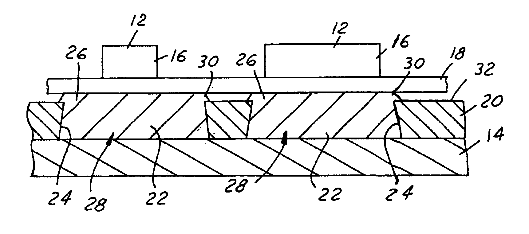
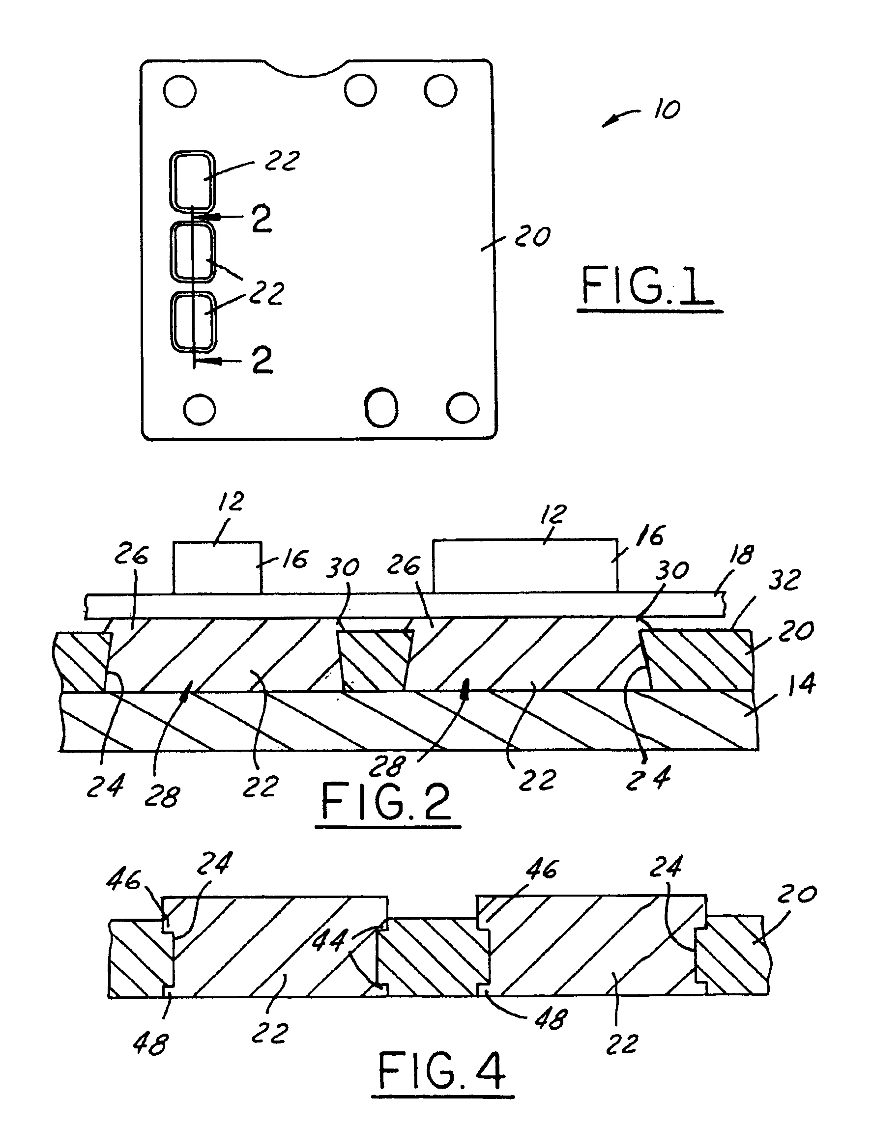
[0014]Referring now to FIG. 1, which is an illustration of a heat sink buffer configuration 10 in accordance with the present invention. Heat sink buffers 10 are well known in the prior art and are commonly utilized to provide thermal communication between a heat generating device 12 and a cold-plate 14 (see FIG. 2). A wide variety of both heat generating devices 12 and cold-plate 14 designs are well known by the prior art and contemplated by the present invention. In one common embodiment, the heat generating device 12 is an electronic component 16 mounted on a substrate 18. Often these components generate excess heat that must be properly dissipated in order for the electronic component 16 to function properly. The thermal energy is therefore transferred out of the electronic component 16 and into the cold-plate 14. Heat sink buffers 10 are utilized to provide both a thermal mounting surface for the electronic component 16 as well as provide a thermal communication link to the co...


PUM


Abstract

A heat sink buffer 10 is provided, including a backplate 20 defining a heat transfer passage 24. A thermally conductive buffer element 22 is positioned within and secured to the heat transfer passage 24 to provide a thermal conduit through the backplate 20.

Description

TECHNICAL FIELD[0001]The present invention relates generally to an improved heatsink configuration and more particularly to an improved heatsink configuration with a conductive buffer.BACKGROUND OF THE INVENTION[0002]Electronics assemblies are formed in a wide variety of configurations for a wide variety of applications. Often, however, they are comprised of a plurality of individual electronic components mounted on a circuit board or other substrate. The individual electronic components typically communicate electronically with each other through the substrate to form a useful electronic assembly. Although the individual electronic components themselves may come in a wide variety of embodiments, one particular type is commonly referred to as a power device. Power devices are electronic components that generate heat during operation. Commonly, the thermal energy generated by these power devices must be dissipated in order for the electronic assembly to function properly. Some power ...

Claims


Application Information

Patent Timeline
IPC IPC(8): H01L23/367H01L23/34H01L21/48
CPCH01L21/4878H01L21/4882H01L23/3677H01L2924/0002H01L2924/00
Inventor EYTCHESON, CHARLES T.HOUK, LARRY WILLIAMMUMMERT, RICK B.
Owner DELPHI TECH IP LTD
Why Eureka
Try Eureka