Method of and apparatus for directional drilling

a directional drilling and apparatus technology, applied in the field of oil and gas well drilling, can solve the problems of difficult to overcome friction, high cost of drilling a well, and high cost of drilling a well, and achieve the effect of reducing friction between the drill string and the bore hol

Inactive Publication Date: 2005-07-19
SCHLUMBERGER TECH CORP
View PDF3 Cites 84 Cited by
  • Summary
  • Abstract
  • Description
  • Claims
  • Application Information

AI Technical Summary

Benefits of technology

[0011]The present invention, in one aspect, provides a method for directional drilling that reduces the friction between the drill string and the bore hole. According to the present invention, a downhole drilling motor is connected to a drilling rig at the surface by a drill string. The drilling motor is oriented at a selected tool face angle. The drill string is rotated at the surface in a first direction until a first torque magnitude is reached without changing the tool face angle. The drill string is then rotated in the opposite direction until a second torque magnitude is reached, again without changing the tool face angle. The drill string is rocked back and forth between the first and second torque magnitudes. Pressure inside the drill string is measured, and the first and second torque magnitudes are adjusted in response to changes in the pressure.

Problems solved by technology

It is very expensive to drill bore holes in the earth such as those made in connection with oil and gas wells.
The cost of drilling a well is primarily time dependent.
Several problems in directional drilling are caused by the fact that a substantial length of the drill string is in frictional contact with and supported by the bore hole.
Since the drill string is not rotating in sliding drilling mode, it is difficult to overcome the friction.
The difficulty in overcoming the friction makes it difficult for the driller to apply sufficient weight to the bit to achieve an optimal rate of penetration.
The drill string also typically exhibits stick / slip friction such that when a sufficient amount of weight is applied to overcome the friction, the drill the weight on bit tends to overshoot the optimum magnitude, and in some cases the applied weight to the bit may be such that the torque capacity of the drilling motor is exceeded.
Exceeding the torque capacity of the drilling motor may cause the motor to stall.
Motor stalling is undesirable because the motor cannot drill when stalled.
Moreover, stalling lessens the life of the drilling motor.
Moreover, when the driller applies drill string angle corrections at the surface in an attempt to correct the tool face angle, a substantial amount of the angular change is absorbed by friction without changing the tool face angle in stick / slip fashion.
A limitation to using surface angle alone as basis for rocking the drill string is that it does not account for the friction between the wall of the bore hole and the drill string.
Rocking to a selected angle may either not reduce the friction sufficiently to be useful, or may exceed the friction torque of the drill string in the bore hole, thus unintentionally changing the tool face angle of the drilling motor.
Further, rocking the tool face angle alone may result in motor stalling if too much weight is suddenly transferred to the bit as friction is overcome.

Method used


Image

  • Method of and apparatus for directional drilling
  • Method of and apparatus for directional drilling
  • Method of and apparatus for directional drilling

Examples


Embodiment Construction

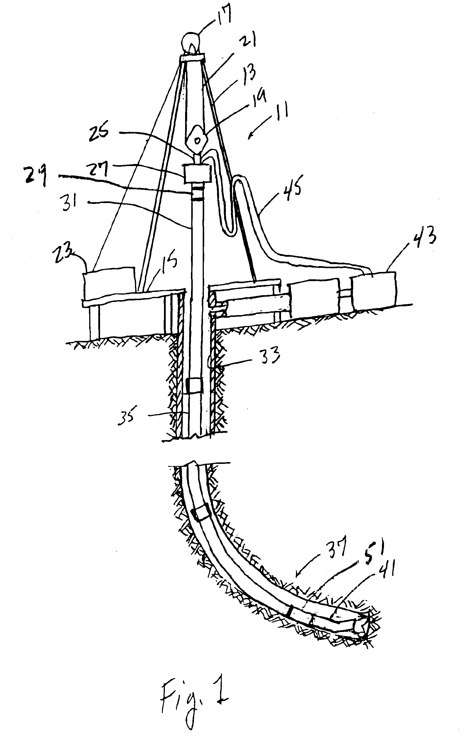
[0015]Referring to FIG. 1, a drilling rig is designated generally by reference numeral 11. The rig 11 in FIG. 1 is depicted as a “land” rig. However, as will be apparent to those skilled in the art, the method and system of the present invention will find equal application to non-land rigs, such as jack-up rigs, semisubmersible rigs, drill ships, and the like.

[0016]The rig 11 includes a derrick 13 that is supported on the ground above a rig floor 15. The rig 11 includes lifting gear, which includes a crown block 17 mounted to the derrick 13 and a traveling block 19. The crown block 17 and the traveling block 19 are interconnected by a cable 21 that is driven by a drawworks 23 to control the upward and downward movement of the traveling block 19. The traveling block 19 carries a hook 25 from which is suspended a top drive 27. The top drive 27 supports a drill string, designated generally by the numeral 35, in a well bore 33. The top drive 27 can be operated to rotate drill string 31 ...


PUM


Abstract

A method of and system for directional drilling reduces the friction between the drill string and the well bore. A downhole drilling motor is connected to a drilling rig at the surface by a drill string. The drilling motor is oriented at a selected tool face angle. The drill string is rotated at the surface in a first direction until a first torque magnitude is reached without changing the tool face angle. The drill string is then rotated in the opposite direction until a second torque magnitude is reached, again without changing the tool face angle. The drill string is rotated back and forth between the first and second torque magnitudes. Pressure inside the drill string is measured, and the first and second torque magnitudes are adjusted in response to changes in the pressure.

Description

CROSS-REFERENCE TO RELATED APPLICATIONS[0001]This is a continuation-in-part of application Ser. No. 10 / 325,639, Dec. 19, 2002, and titled METHOD OF AND APPARATUS FOR DIRECTIONAL DRILLING. The present application claims the benefit of Provisional Application Ser. No. 60 / 469,293, filed May 10, 2003, and titled METHOD OF AND APPARATUS FOR DIRECTIONAL DRILLING.FIELD OF THE INVENTION[0002]The present invention relates generally to the field of oil and gas well drilling. More particularly, the present invention relates to a method of and system for directional drilling in which the drill string is rotated back and forth between selected surface measured torque magnitudes without changing the tool face angle or changing the tool face angle to a desired value, thereby to reduce friction between the drill string and the well bore.BACKGROUND OF THE INVENTION[0003]It is very expensive to drill bore holes in the earth such as those made in connection with oil and gas wells. Oil and gas bearing ...

Claims


Application Information

Patent Timeline
Patent Type & Authority Patents(United States)
IPC IPC(8): E21B7/04E21B7/06E21B44/00E21B44/04
CPCE21B7/068E21B44/00E21B44/04
Inventor HACI, MARCMAIDLA, ERIC E.
Owner SCHLUMBERGER TECH CORP
Why Eureka
Try Eureka