Reduced torque gate valve with roller screw

a gate valve and roller screw technology, applied in the field of gate valves, can solve the problems of increased cost and complexity, increased force, and more torque to be applied to the handwheel than is practical to exert, and achieve the effect of raising and lowering the ga

Inactive Publication Date: 2005-07-19
FMC TECH INC
View PDF8 Cites 27 Cited by
  • Summary
  • Abstract
  • Description
  • Claims
  • Application Information

AI Technical Summary

Benefits of technology

[0014]In comparison to prior art gate valves, the roller screw assembly requires substantially fewer turns of the handwheel in order to raise and lower the gate. Thus, assuming the operator turns the handwheel at a constant rate, the gate in the gate valve of the present invention will rise substantially faster than the gates in prior art gate valves. Consequently, any erosion of the gate which may occur when the opening first intersects the flow bore will be minimized.

Problems solved by technology

Unfortunately, for many large or high pressure valves which require large actuating forces, this method requires more torque to be applied to the handwheel than is practical to exert by hand.
This pressure differential results in very high forces which push the gate against the downstream seat.
The disadvantages of balanced stem gate valves include increased cost and complexity and the creation of an additional potential leak path between the second stem and its corresponding stem packing.
The disadvantage of this configuration is that when the valve is moved from the closed position to the open position, both the unbalanced stem force and the maximum gate-to-seat drag forces must be overcome simultaneously.
One disadvantage of these devices is that, in order to sufficiently reduce the required torque on the handwheel, the gear ratio must be very high.
Consequently, a large number of turns is required to open or close the valve.
Moreover, since the rate at which an operator can turn the handwheel is limited, the gate necessarily traverses very slowly from one position to the other.
This relatively slow traverse is especially troublesome when moving the gate from the closed position to the open position.
In many cases, the fluid may contain abrasive particles which tend to erode the valve components during high velocity flow.
Thus, the slower the gate moves to the open position, the greater the amount of erosion.
A further disadvantage of the gate valves shown in the Williams et al., Pierce, Jr. and Karr, Jr. patents is that these valves must be in the closed position in order to backseat the stem against the bonnet.

Method used


Image

  • Reduced torque gate valve with roller screw
  • Reduced torque gate valve with roller screw
  • Reduced torque gate valve with roller screw

Examples


Embodiment Construction

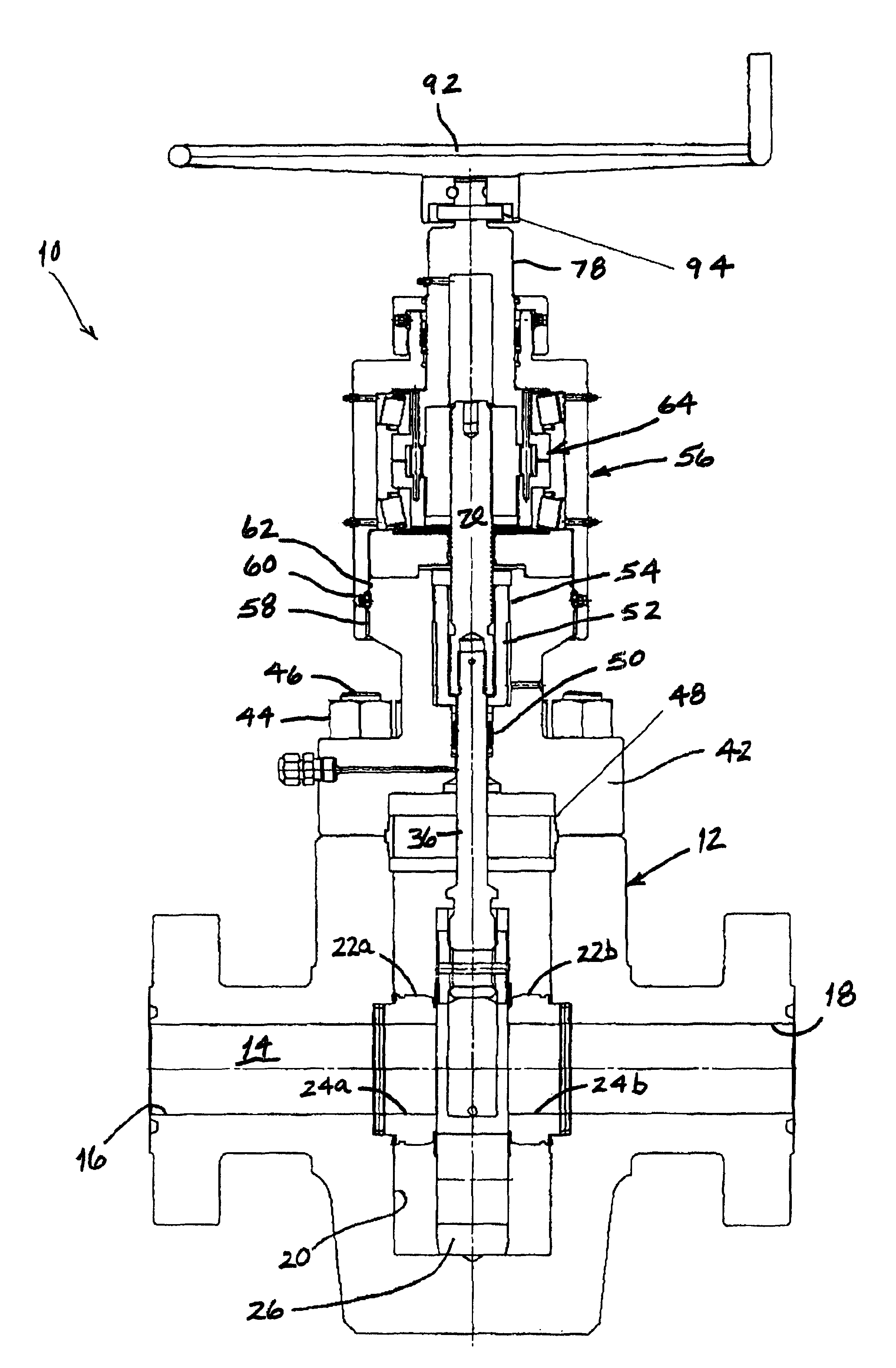
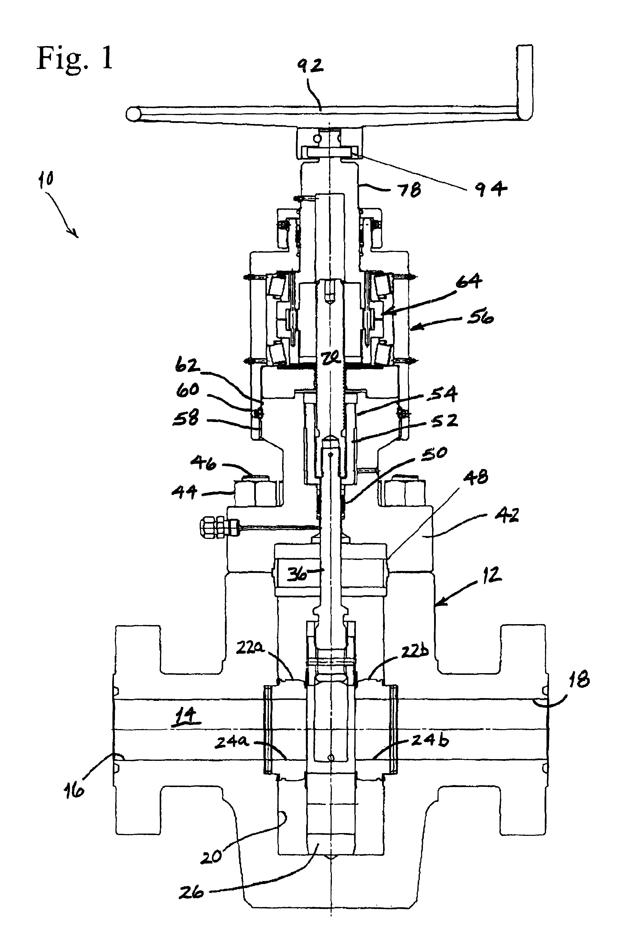
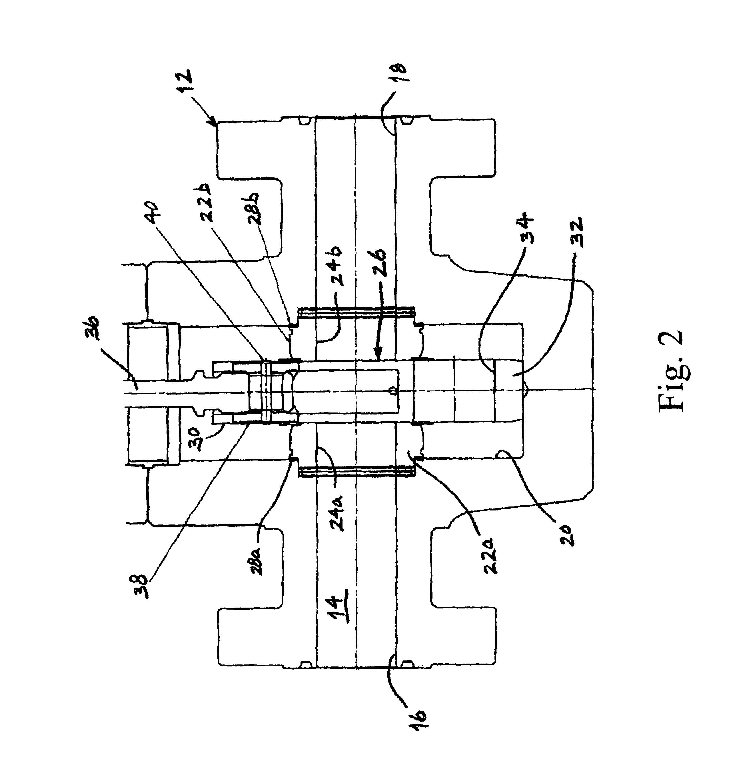
[0019]Referring to FIG. 1, the gate valve of the present invention, which is indicated generally by reference number 10, is shown to comprise a valve body 12 which comprises a flow bore 14 that extends longitudinally through the valve body between a first port 16 and a second port 18 and a gate cavity 20 that extends partially through the valve body generally transverse to the flow bore. The gate valve 10 also comprises a pair of seats 22a, 22b, each of which is positioned at least partially in a corresponding seat pocket that is formed at the intersection of the flow bore 14 and the gate cavity 20. Each seat 22a, 22b includes a transverse bore 24a, 24b that is aligned with the flow bore 14 to thereby define a flow passage through the valve body 12.

[0020]Referring also to FIG. 2, the gate valve 10 further includes a gate 26 which is slidably disposed between the seats 22a, 22b, each of which is preferably urged into contact with the gate by a respective Belleville spring 28a, 28b. T...


PUM


Abstract

A gate valve is disclosed which comprises a valve body which includes a flow bore that extends completely therethrough and a gate cavity that extends partially therethrough and intersects the flow bore, a bonnet which is connected to the valve body over the gate cavity, a gate which is disposed in the gate cavity across the flow bore and includes a transverse opening that extends completely therethrough, a valve stem which includes a first portion that is connected to the gate and a second portion that extends through the gate cavity, a handwheel, and a roller screw assembly which is connected between the handwheel and the second portion of the valve stem and which converts rotation of the handwheel into translation of the valve stem. In this manner, translation of the valve stem raises or lowers the gate to bring the opening into or out of alignment with the flow bore to either open or close the gate valve, respectively.

Description

[0001]This application is based on U.S. Provisional Patent Application No. 60 / 314,985, which was filed on Aug. 24, 2001.BACKGROUND OF THE INVENTION[0002]The present invention is directed to a gate valve. More particularly, the invention is directed to a manually actuated, rising stem gate valve which includes a roller screw assembly to efficiently convert rotation of the handwheel into translation of the valve stem.[0003]Gate valves are used in a variety of industries to control the flow of fluids. In particular, gate valves are used extensively in the oil and gas industry to control the flow of produced fluids at various stages of production. Most gate valves used in this industry comprise a valve body having a longitudinal flow bore and a transverse gate cavity that intersects the flow bore. A gate having a gate opening extending transversely therethrough is disposed in the gate cavity. A stem is provided for moving the gate between an open position, in which the gate opening is a...

Claims


Application Information

Patent Timeline
Patent Type & Authority Patents(United States)
IPC IPC(8): F16K31/44F16K31/50F16K3/02
CPCF16K3/0254F16K31/508
Inventor HALLDEN, DONALD F.CAIN, DAVID E.GLIDDEN, GREGORY L.SCOTT, WILLIAM L.
Owner FMC TECH INC
Why Eureka
Try Eureka