Apparatus for assisting operator in performing manual operations in connection with component feeders

Inactive Publication Date: 2005-07-19
FUJI MASCH MFG CO LTD
View PDF5 Cites 23 Cited by
  • Summary
  • Abstract
  • Description
  • Claims
  • Application Information

AI Technical Summary

Benefits of technology

[0012]The mounting-position checking and indicating device may include a detecting device of non-contact type operable to effect the above-indicated determination, without a contact with the relevant component or a detecting device of contact type operable to effect the above-indicated determination, by contacting the relevant component feeder. The detecting device of non-contact type is preferably selected from among various proximity switches, and various photoelectric switch of light-reflecting or light-transmission type each including a light-emitting element and a light-receiving element.
[0013]The mounting-position checking and indicating device provides an indication that the relevant component

Problems solved by technology

However, there is a risk that the operator erroneously reads the identification number indicated on the display screen, or fails to correctly recognize the feeder-mounting position indicated by the indicator arrow, due to observation of the indicator arro

Method used


Image

  • Apparatus for assisting operator in performing manual operations in connection with component feeders
  • Apparatus for assisting operator in performing manual operations in connection with component feeders
  • Apparatus for assisting operator in performing manual operations in connection with component feeders

Examples


first embodiment

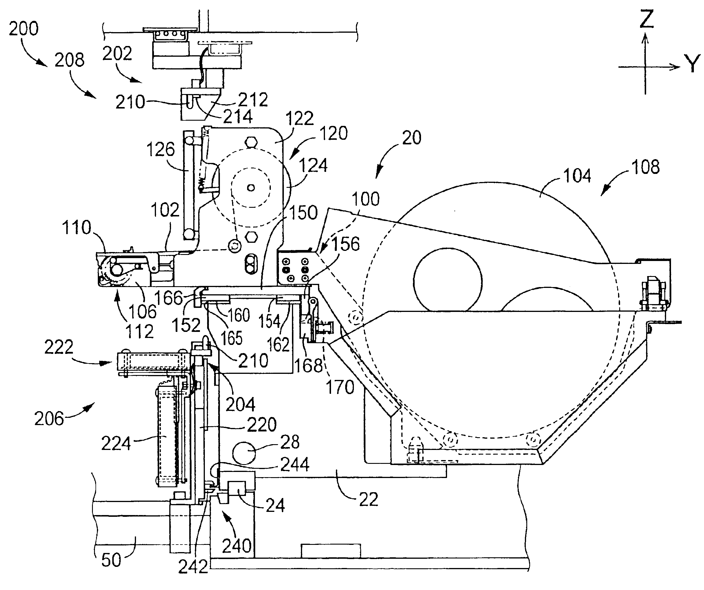
[0102]In the first embodiment described above, each tape feeder 20 presently mounted on the table 22, 23 is replaced with a new one in either one of the two cases: when all of the electronic components accommodated in that tape feeder 20 have been used; and when the number of the electronic components left in the tape feeder 20 has become smaller than a predetermined lower limit. However, the replacement may be effected in only one of those two cases. Further, when a need to immediately replace any tape feeder 20 is detected, any other tape feeders which are expected to be replaced in the near future may be replaced together with the tape feeder that is required to be immediately replaced. For instance, when a tape feeder whose number of electronic components has become smaller than a predetermined first value (predetermined lower limit) is replaced, any tape feeders whose numbers of electronic components have become smaller than a predetermined second value larger than the first va...

second embodiment

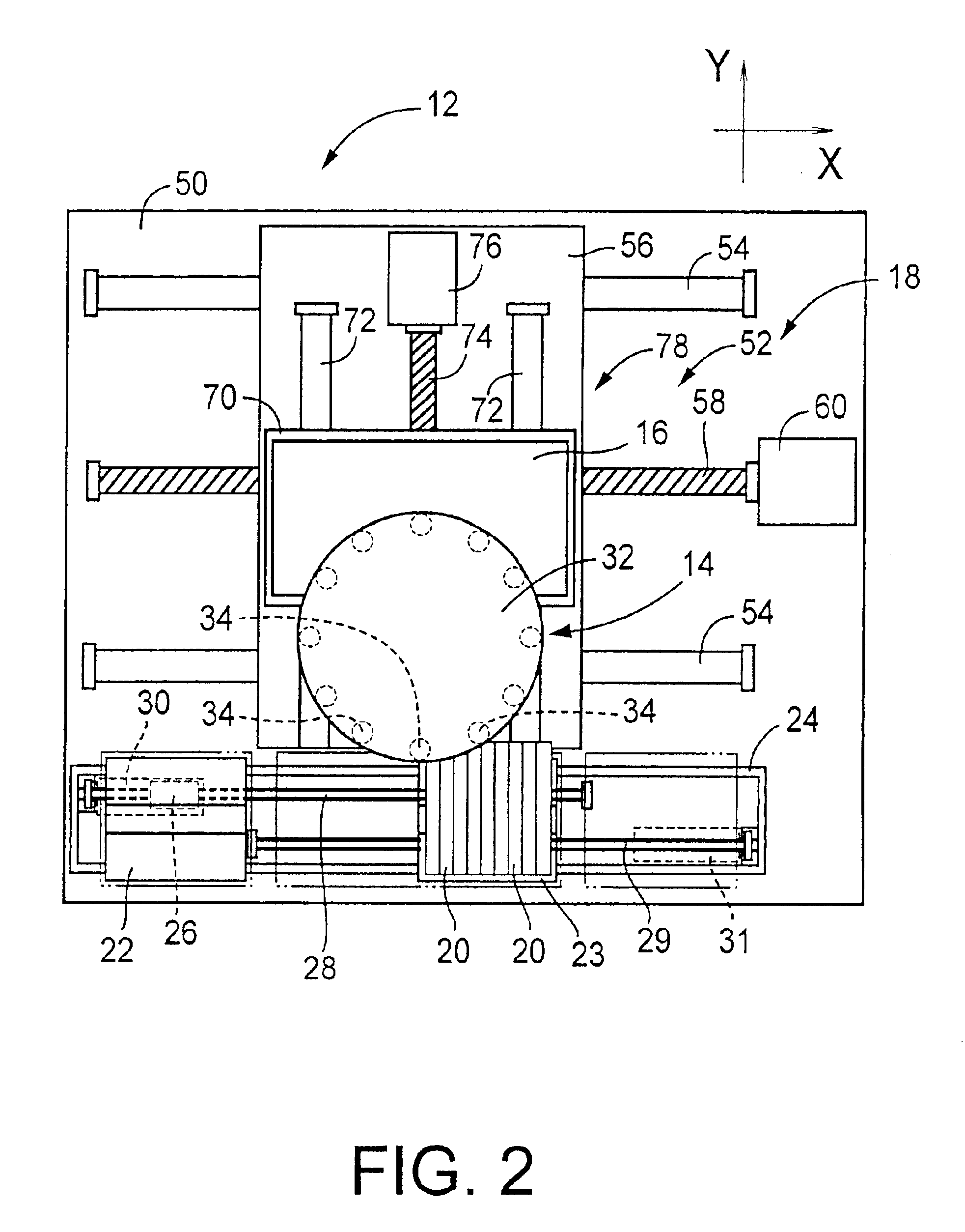
[0106]In the present second embodiment of FIG. 9, the two electronic-component supply devices 406, 408 are used to supply respective sets of electronic components of the same kinds, so that the electronic components necessary to produce printed-circuit boards of the same type may be supplied by a selected one of the two devices 406, 408. In this arrangement, when one of the two devices 406, 408 becomes inoperable to supply the electronic components, the other device 406, 408 may be operated to supply the necessary electronic components, without an interruption of a component supplying operation in the system.

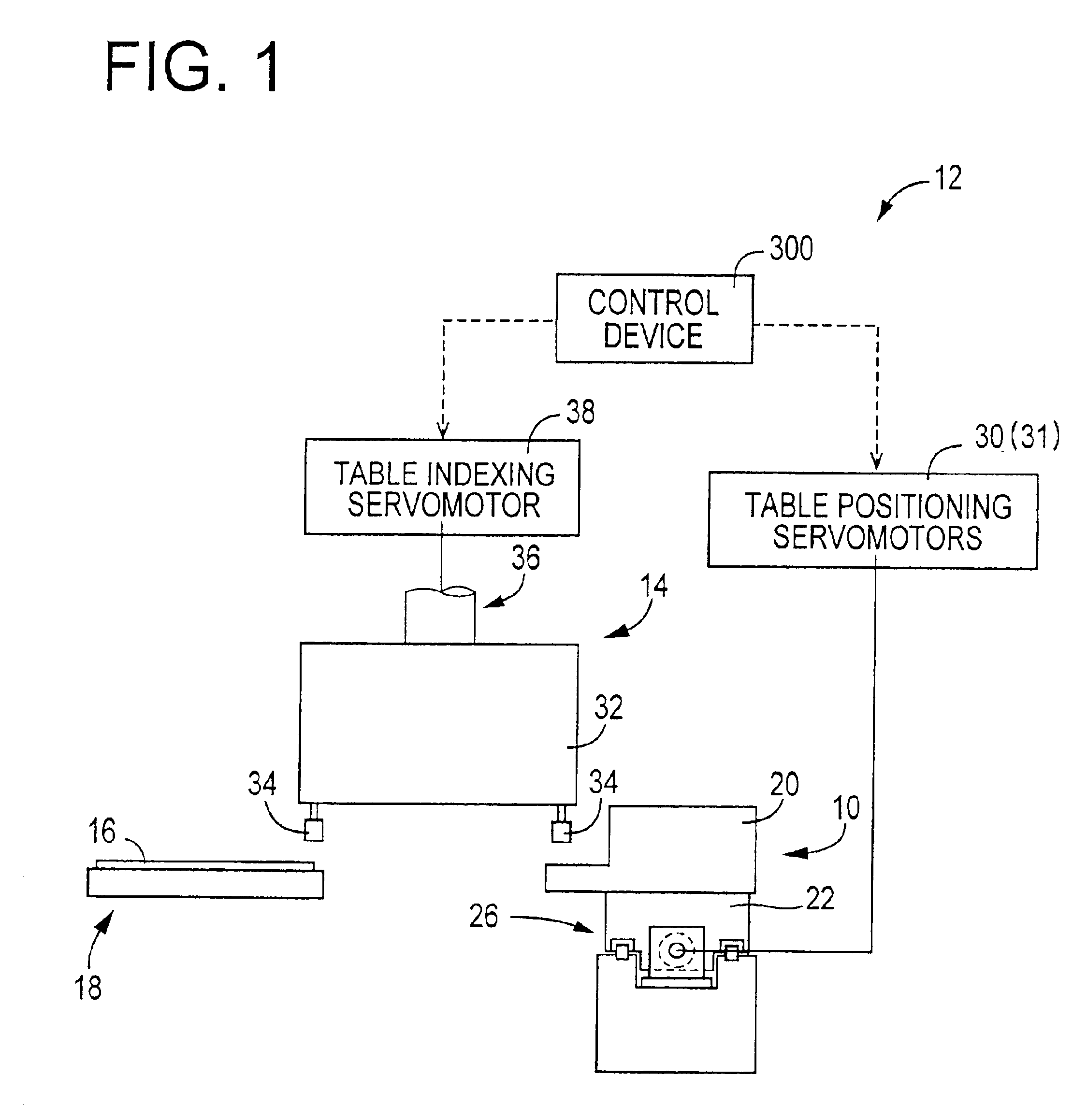
[0107]On the machine base 400, there is also disposed an electronic-component mounting device including a component mounting head 450 which will be described. The electronic components supplied by the electronic-component supply devices 406, 408 are mounted by the component mounting head 450, on the printed-wiring board 16 to produce a printed-circuit board. On the machine base ...


PUM


Abstract

An apparatus for assisting an operator of an electric-component supply device including component feeders mounted on feeder support and each accommodating electric components, the apparatus including (a) a position indicator operable to indicate the feeder-mounting position at which the component feeder is to be mounted on the feeder support, and/or the feeder-mounting position at which the component feeder has been removed from the feeder support, and/or (b) a feeder indicator operable to indicate at least one of (i) the component feeder which has been mounted on the feeder support, (ii) the component feeder which is to be removed from the feeder support and (iii) the component feeder on which an intermediate operation is required to be performed between moments of the operations to mount and remove the component feeder on and from the feeder support.

Description

BACKGROUND OF THE INVENTION[0001]1. Field of the Invention[0002]The present invention relates to an operator assisting apparatus arranged to assist an operator of an electric-component supply device including a plurality of component feeders and feeder support on which the component feeders are mounted at respective feeder-mounting positions. Each of the component feeders accommodates a plurality of electric components (typically, electronic components) of a specific kind, and is arranged to successively supply the electric components one after another. The operator assisting apparatus is arranged to assist the operator in performing manual working operations such as mounting or setting and removal of the component feeders on and from the feeder support, so as to avoid erroneous or inadequate manual working operations or improve the working efficiency.[0003]2. Discussion of Related Art[0004]To maintain such an electric-component supply device in an operable condition, the operator i...

Claims


Application Information

Patent Timeline
IPC IPC(8): H05K13/04H05K13/02
CPCH05K13/0417H05K13/08Y10T29/53174Y10T29/49133Y10T29/53178Y10S414/137H05K13/0857H05K13/0888H05K13/086
Inventor KAWAI, TAKAYOSHISUHARA, SHINSUKETSUCHIYA, YUSUKE
Owner FUJI MASCH MFG CO LTD
Why Eureka
Try Eureka