
Connector capable of preventing incomplete fitting

a technology of connecting rods and connectors, applied in the direction of incorrect coupling prevention, coupling device connection, electrical apparatus, etc., can solve problems such as incomplete fitting state, and achieve the effect of enhancing productivity

Active Publication Date: 2005-07-19
YAZAKI CORP
View PDF8 Cites 17 Cited by
  • Summary
  • Abstract
  • Description
  • Claims
  • Application Information

AI Technical Summary

Benefits of technology

The invention provides a connector that can reliably engage with another connector without inducing a working error. This is achieved through a flexible lock arm and a tubular fitting detector that can slide between a first and second position. The fitting detector has a retainer that can engage with the lock arm in both positions, allowing for easy sliding between the two housings. The connector also has a finger pad on the fitting detector to prevent the operator's finger from pressing the housing during the fitting operation. The invention also includes a guide projection on the fitting detector to ensure smooth displacement without hitting the operator's finger. The guide projection is extended from the bridge member in a sliding direction of the fitting detector. This improves productivity without increasing the number of molding processes.

Problems solved by technology

However, the connector 50 has had a problem that when the fitting detector 70 slides relative to the female connector housing 60, the female connector housing 60 may be pressed with a hand or fingers of an operator who is conducting the fitting work, and in some cases, the fitting detector 70 may not slide relative to the female connector housing 60, resulting in the incomplete fitting state.

Method used


Image

  • Connector capable of preventing incomplete fitting
  • Connector capable of preventing incomplete fitting
  • Connector capable of preventing incomplete fitting

Examples


Embodiment Construction

[0031]One preferred embodiment of the invention will be described below in detail with reference to the accompanying drawings.

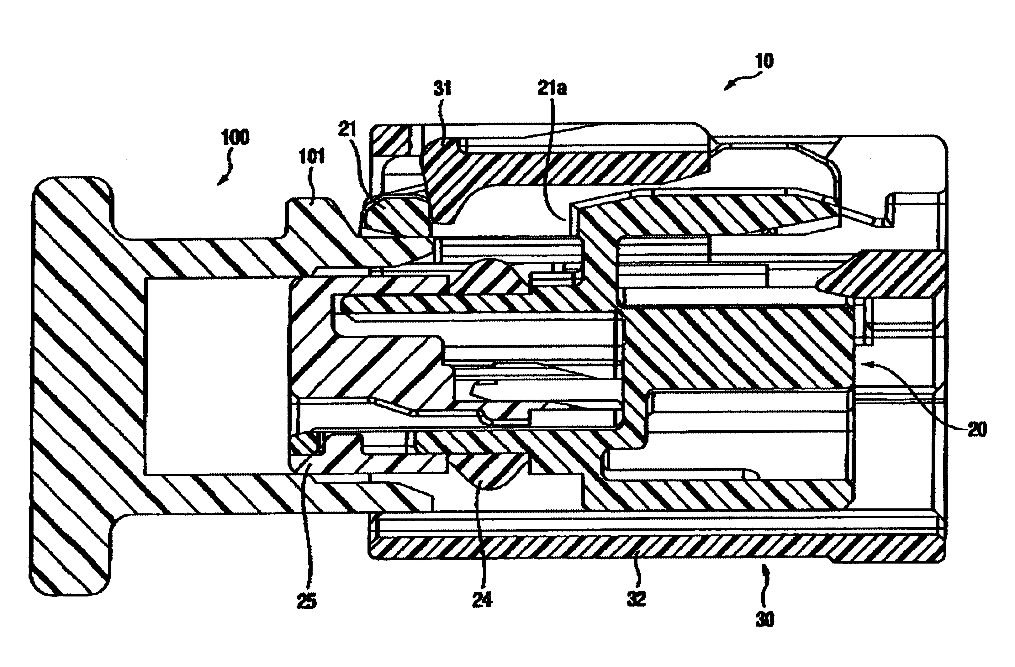
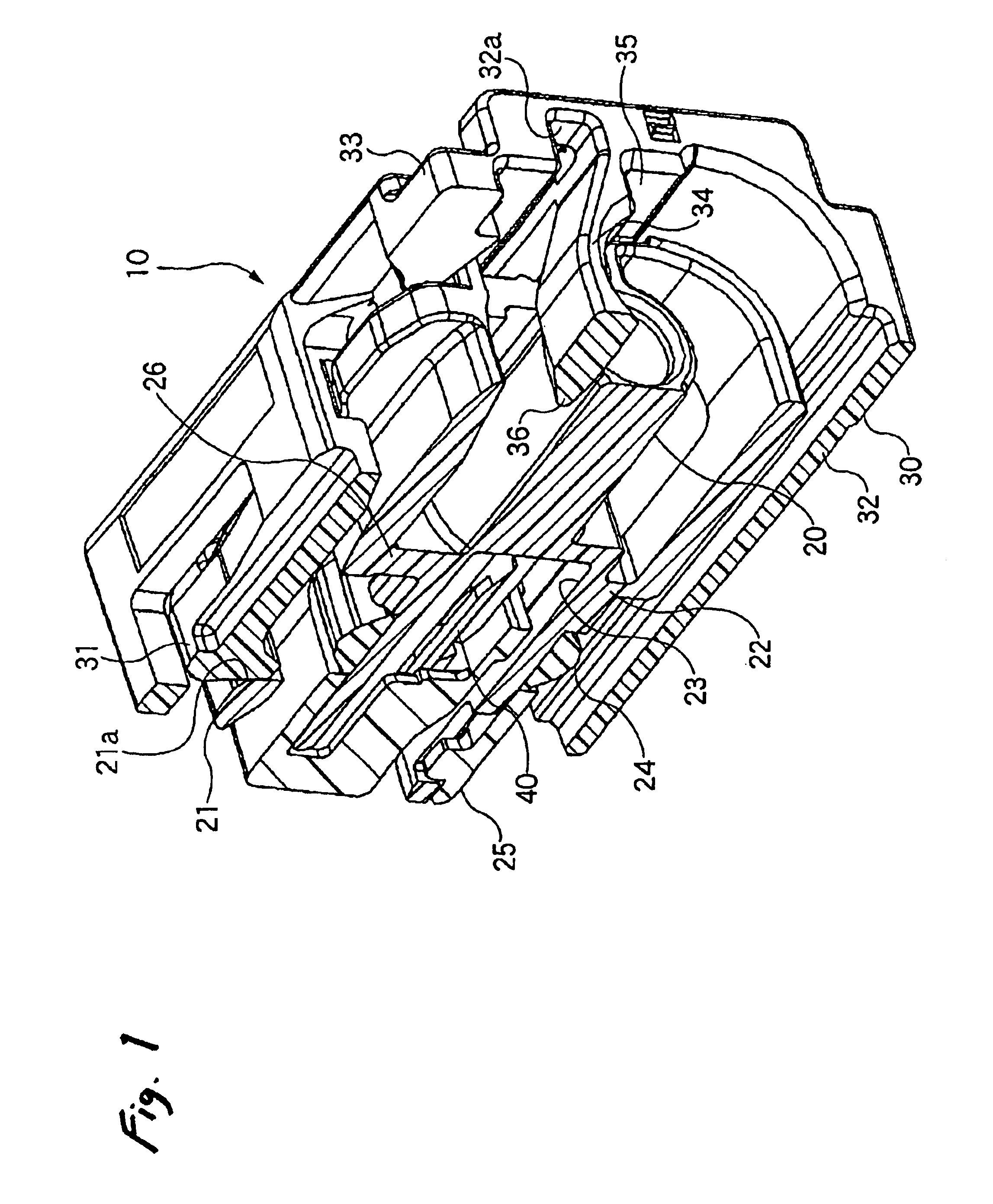
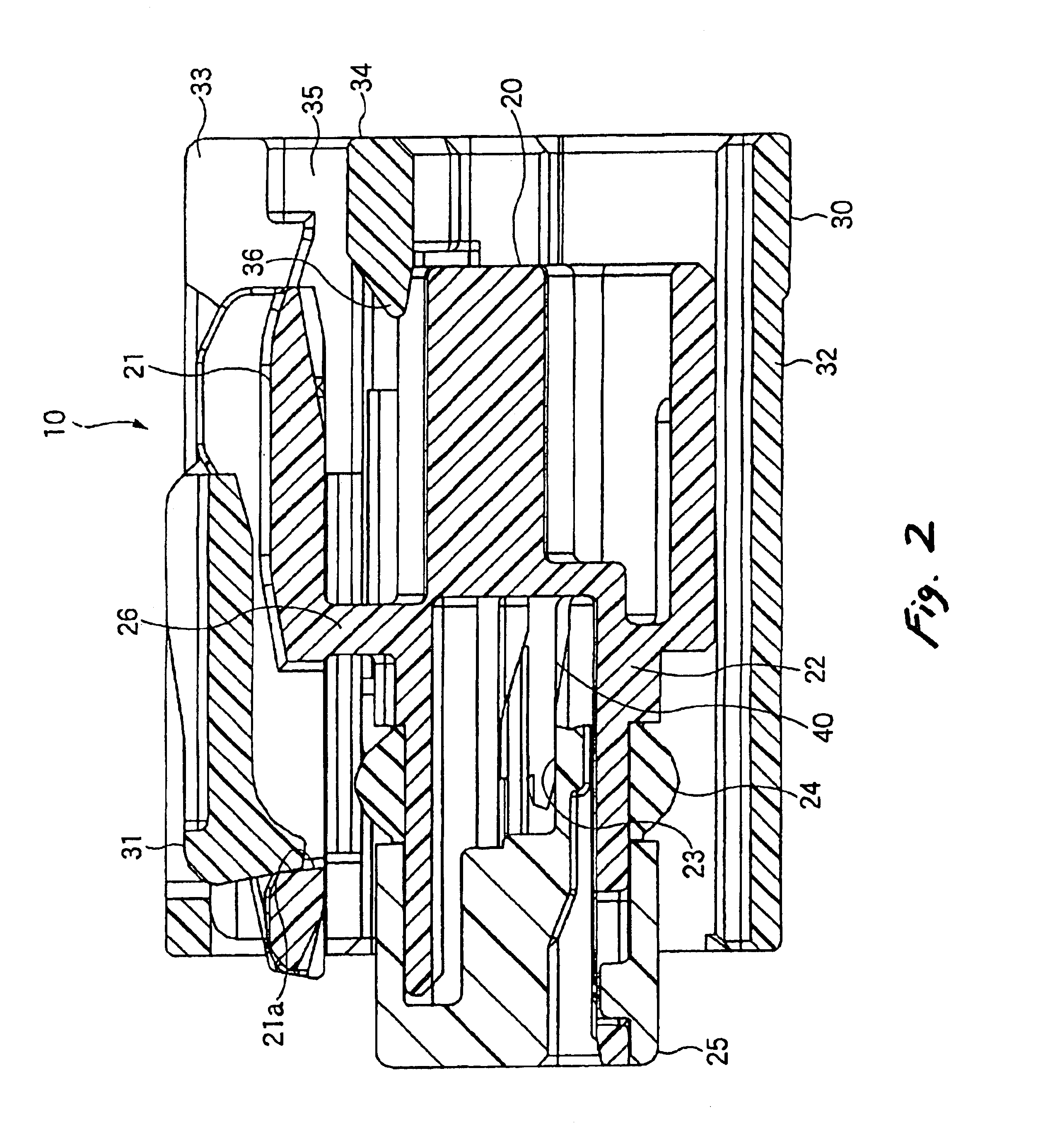
[0032]As showing in FIG. 1, a connector 10 in this embodiment comprises a female connector housing 20 which is a connector housing having a flexible lock arm 21, and a fitting detector 30 in a substantially tubular shape fitted around the female connector housing 20 slidably in a fitting direction. The fitting detector 30 is provided with a retainer 31 adapted to be engaged with the flexible lock arm 21. A male connector housing 100, shown in FIG. 6, is adapted to be fitted to the female connector housing 20.

[0033]As shown in FIG. 2, the female connector housing 20 includes a housing body 22 in a substantially cylindrical shape in which terminal chambers 23 for containing and holding female terminals 40 are formed. A front holder 25 is fitted into the housing body 22 by way of an O-ring 24 from the front.

[0034]The flexible lock arm 21 is arranged on an upper ...


PUM


Abstract

A first connector housing is provided with a flexible lock arm. A tubular fitting detector is fitted to an outer periphery of the first connector housing while being slidable thereon between a first position and a second position. A retainer is provided on the fitting detector, and adapted to be engaged with a first portion of the lock arm in a case where the fitting detector is placed at the first position, and engaged with a second portion of the lock arm in a case where the fitting detector is placed at the second position. A second connector housing is provided with a projection adapted to release the engagement between the retainer and the first portion of the lock arm in a case where the second connector housing is completely fitted with the first connector housing, so that the fitting detector is allowed to slide from the first position to the second position. A finger pad is provided on the fitting detector, and arranged such that an operator's finger is placeable thereon while being separated from at least the lock arm, during a fitting operation between the first connector housing and the second connector housing.

Description

BACKGROUND OF THE INVENTION[0001]The present invention relates to a connector capable of preventing incomplete fitting, and more particularly, to a connector which detects an incomplete fitting state between a pair of female connector housing and male connector housing, based on whether a fitting detector provided on one of the connector housings can slide up to a predetermined position when the connector housings are fitted with each other.[0002]FIGS. 4 and 5 show a related-art connector 50 of such a type. A female connector housing 60 which is one of the connector housings constituting the connector 50 is provided with a fitting detector 70 which is fitted to the female connector housing 60 so as to surround an outer periphery thereof. The fitting detector 70 is formed with a retainer 71 in an upper part thereof.[0003]The female connector housing 60 contains a plurality of female terminals 62 inside a main body 61 and is provided with a flexible lock arm 64 having a hole 63. Moreo...

Claims


Application Information

Patent Timeline
Patent Type & Authority Patents(United States)
IPC IPC(8): H01R13/641H01R13/703H01R13/627H01R13/64H01R13/70H01R13/639
CPCH01R13/6272H01R13/641H01R13/7031
Inventor ENDO, TOMOMINISHIDA, ATSUSHIKASHIMA, YOSHITAKAMINAKATA, MASATOITO, KEIICHI
Owner YAZAKI CORP
Learn More