Microfluidic analytical devices and methods

a microfluidic and analytical device technology, applied in the field of microfluidic analysis devices and methods, can solve the problems of high tool-up costs for both of these techniques, complex biochemical reactions, and inability to quickly prototyping and manufacture flexibility

Active Publication Date: 2005-07-19
AGILENT TECH INC
View PDF54 Cites 92 Cited by
  • Summary
  • Abstract
  • Description
  • Claims
  • Application Information

AI Technical Summary

Problems solved by technology

In particular, when conducted in microfluidic volumes, complicated biochemical reactions may be carried out using very small volumes of liquid.
Imprinting methods in PMMA have also been demonstrated (see, Martynova et.al., Analytical Chemistry (1997) 69: 4783-4789) However, these techniques do not lend themselves to rapid prototyping and manufacturing flexibility.
Moreover, the tool-up costs for both of these techniques are quite high and can be cost-prohibitive.
Attempts to conduct separations or detections in microfluidic volumes have been stifled by difficulties such as making such tools in microfluidic scale and then integrating such tools into microfluidic devices.
Another difficulty is accurately measuring stoichiometric microfluidic volumes of reagents and solvents to perform analyses on a microfluidic scale.
Additionally, difficulties in rapidly prototyping microfluidic devices are compounded by attempts to incorporate multiple analytical tools.
Applying conventional mixing strategies to microfluidic volumes is generally ineffective, impractical, or both.
In the laminar regime, using conventional geometric modifications such as baffles is generally ineffective for promoting mixing.
Moreover, the task of integrating moveable stirring elements and / or their drive means in microfluidic devices would be prohibitively difficult using conventional means due to volumetric and / or cost constraints, in addition to concerns regarding their complexity and reliability.

Method used


Image

  • Microfluidic analytical devices and methods
  • Microfluidic analytical devices and methods
  • Microfluidic analytical devices and methods

Examples


Embodiment Construction

Definitions:

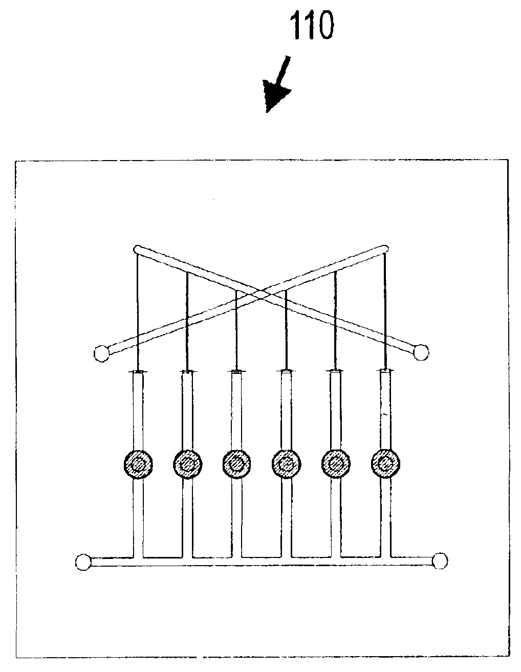
[0031]The term “channel” or “chamber” as used herein is to be interpreted in a broad sense. Thus, it is not intended to be restricted to elongated configurations where the transverse or longitudinal dimension greatly exceeds the diameter or cross-sectional dimension. Rather, such terms are meant to comprise cavities or tunnels of any desired shape or configuration through which liquids may be directed. Such a fluid cavity may, for example, comprise a flow-through cell where fluid is to be continually passed or, alternatively, a chamber for holding a specified, discrete amount of fluid for a specified amount of time. “Channels” and “chambers” may be filled or may contain internal structures comprising, for example, valves, filters, and similar or equivalent components and materials.

[0032]The term “detection” as used herein is to be interpreted broadly to include qualitative and / or quantitative methods. Analytical techniques may be used to detect analytes either within a m...


PUM

PropertyMeasurementUnit
lengthaaaaaaaaaa
lengthaaaaaaaaaa
pore sizeaaaaaaaaaa

Abstract

Modular microfluidic systems includes a plurality of microfluidic modules, each capable of performing fluidic operations including, but not limited to, filtering, splitting, regulating pressure, mixing, metering, reacting, diverting, heating, cooling, and condensing are provided. The microfluidic modules are polymeric, stencil-based structures adapted to be coupled in sequence for performing biological or chemical synthesis, including, but not limited to, chemical and biological syntheses of organic, polymer, inorganic, oligonucleotide, peptide, protein, bacteria, and enzymatic products.

Description

STATEMENT OF RELATED APPLICATION(S)[0001]This application claims priority to U.S. Provisional Patent Application Ser. No. 60 / 296,897, filed Jun. 7, 2001 and currently pending.FIELD OF THE INVENTION[0002]The present invention relates to microfluidic analysis devices and methods for their use and manufacture. These devices and methods are useful in performing microfluidic-scale chemical and biological analyses including separations and detections.BACKGROUND OF THE INVENTION[0003]There has been a growing interest in the manufacture and use of microfluidic systems for the acquisition of chemical and biological information. In particular, when conducted in microfluidic volumes, complicated biochemical reactions may be carried out using very small volumes of liquid. Among other benefits, microfluidic systems increase the response time of reactions, minimize sample volume, and lower reagent consumption. When volatile or hazardous materials are used or generated, performing reactions in mic...

Claims


Application Information

Patent Timeline
Patent Type & Authority Patents(United States)
IPC IPC(8): B01L3/00G01N31/00B01F5/06B01F13/00B01J19/00
CPCB01F5/0682B01F13/0059B01J19/0093B01L3/5027B82Y30/00B01F5/0688Y10T436/2575B01J2219/00783B01J2219/0081B01J2219/00822B01J2219/00833B01J2219/00837B01J2219/00867B01J2219/00873B01J2219/00889B01J2219/00891B01J2219/00909B01J2219/00916B01J2219/00934B01J2219/00961B01L3/502707B01L3/502738B01L2300/0681B01L2300/0816B01L2300/0864B01L2300/0867B01L2300/087B01L2300/0887B01L2300/18B01L2400/0487B01L2400/0638B01L2400/084Y10T436/25625Y10T436/25G01N21/05G01N2021/0346G01N2021/056G01N2021/058Y10T137/0491B01F25/45B01F25/4521B01F33/30
Inventor O'CONNOR, STEPHEN D.KARP, CHRISTOPH D.PEZZUTO, MARCICOYNE, COURTNEYHOBBS, STEVEN E.DANTSKER, EUGENE
Owner AGILENT TECH INC
Why Eureka
Try Eureka