Multi-coil induction plasma torch for solid state power supply

a plasma torch and induction technology, applied in plasma welding apparatus, plasma technique, manufacturing tools, etc., can solve the problems of adversely affecting plasma sustainability, inefficient tube-type oscillator power supply, difficult to ignite and run stably induction induction torches, etc., to achieve efficient heat transfer, high thermal conductivity of materials, and high velocity flow

Inactive Publication Date: 2005-07-19
TEKNA PLASMA SYST INC
View PDF17 Cites 186 Cited by
  • Summary
  • Abstract
  • Description
  • Claims
  • Application Information

AI Technical Summary

Benefits of technology

[0018]A cooling fluid supply is connected to the thin annular chamber for establishing a high velocity flow of cooling fluid in this thin annular chamber. The high thermal conductivity of the material forming the confinement tube and the high velocity flow of cooling fluid both contribute in efficiently transferring heat from the plasma confinement tube, heated by the high temperature plasma, into the cooling fluid to thereby efficiently cool the confinement tube.

Problems solved by technology

When operated at a high power level (above 10 kW) and a pressure equal to or higher than one (1) atmosphere, industrial inductive torches are difficult to ignite and to run stably.
Additionally, the presence of two separate induction stages was found to allow hot gases exiting the first stage to be mixed with a different gas which would otherwise adversely affect plasma sustainability.
Tube-type oscillator power supplies are notoriously inefficient with typically 40% of the input power being lost in the oscillator and tank circuit and only 20 to 40% of the input power being available as plasma enthalpy in the hot gas.
Solid state power supplies, however, currently have a characteristic low frequency range of operation (typically between 300 to 400 kHz) and therefore are generally unsuitable for producing the required RF signal to the high frequency coil which is used to inductively ignite the plasma.
Furthermore, existing dual coil designs using tube-type oscillator power supplies result in serious interactions between the control circuits of the two power supplies which can only be resolved by imposing a minimum separation between the coils.

Method used


Image

  • Multi-coil induction plasma torch for solid state power supply
  • Multi-coil induction plasma torch for solid state power supply

Examples


Embodiment Construction

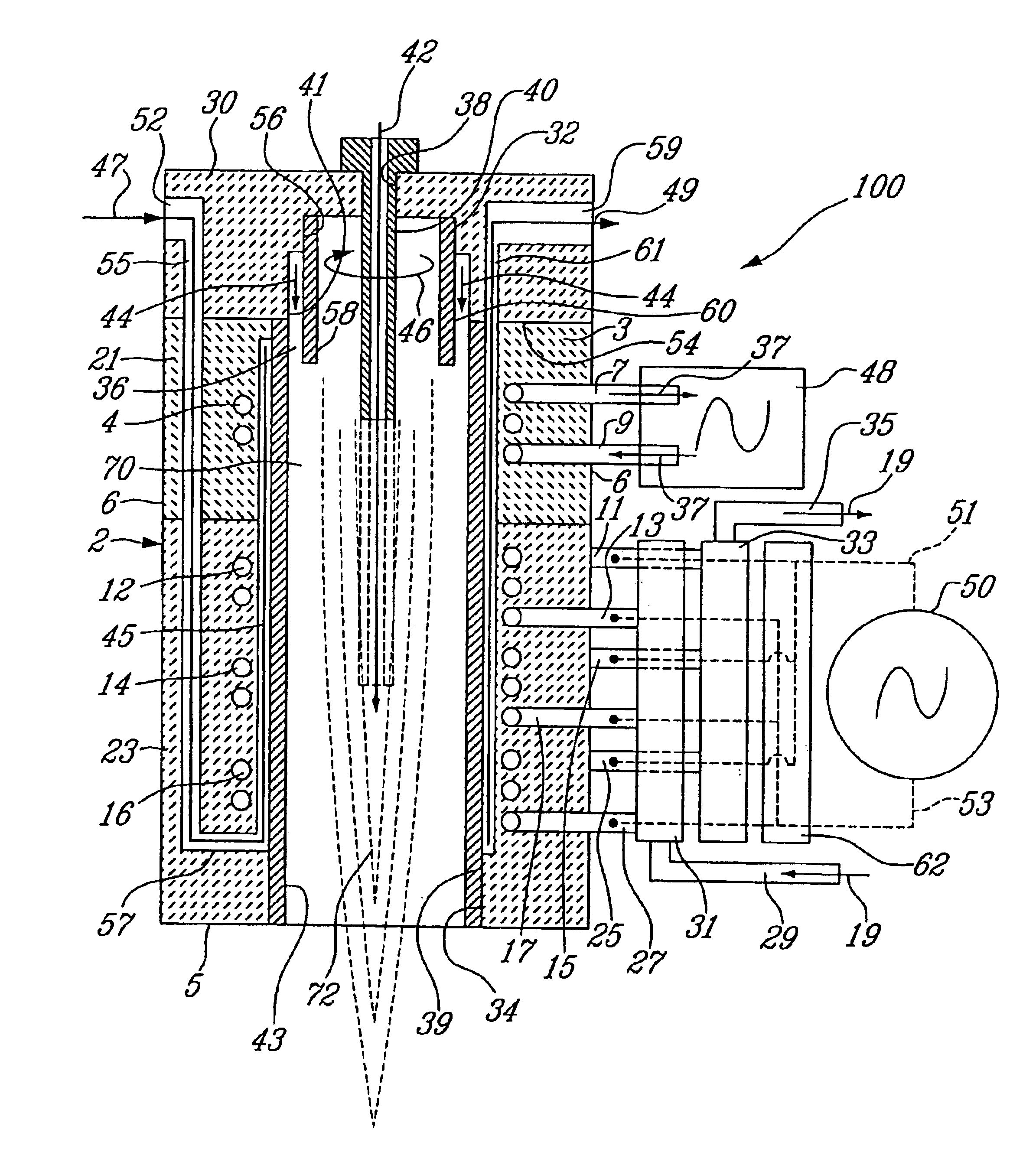
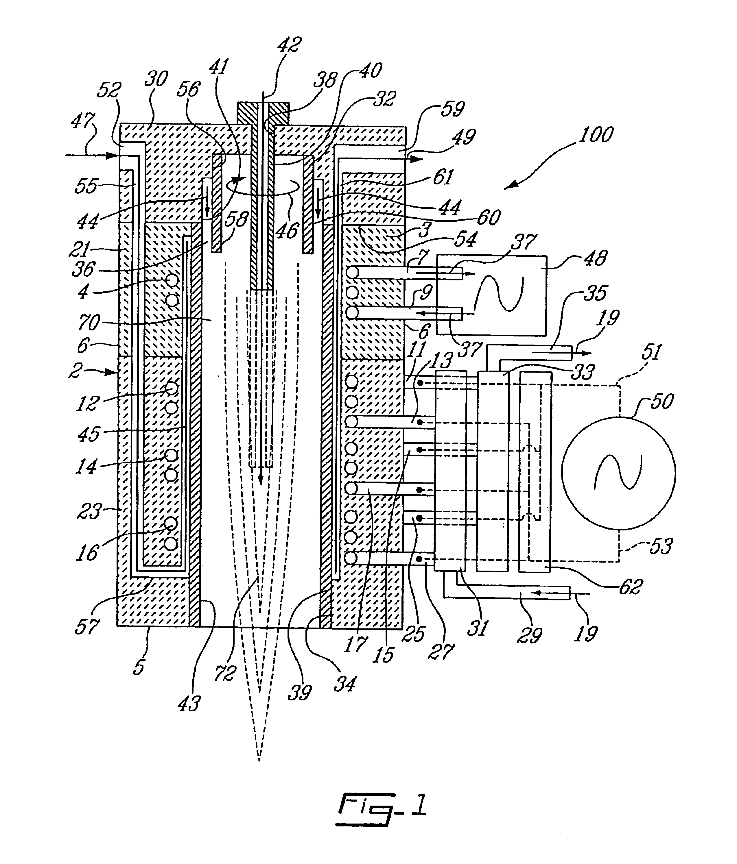
[0029]FIG. 1 shows the illustrative embodiment of multi-coil induction plasma torch generally identified by the reference 100. More specifically, the illustrative embodiment as shown in FIG. 1 forms a high impedance matched multi-coil induction plasma torch capable of generating an inductively coupled gas plasma.

[0030]The multi-coil induction plasma torch 100 of FIG. 1 comprises a tubular (for example cylindrical) torch body 2 made of proximal 21 and distal 23 tubular pieces made of cast ceramic or composite polymer and assembled end to end. Other suitable materials could also be contemplated to fabricate the tubular pieces 21 and 23 of the torch body 2. This tubular torch body 2 has proximal 3 and distal 5 ends, and defines an axial chamber 70 in which a plasma 72 is ignited and sustained.

[0031]Still referring to the illustrative embodiment as shown in FIG. 1, the tubular torch body 2 has an inner cylindrical surface lined with a cylindrical, relatively thin plasma confinement tube...


PUM

PropertyMeasurementUnit
temperatureaaaaaaaaaa
frequencyaaaaaaaaaa
pressureaaaaaaaaaa

Abstract

An induction plasma torch comprises a tubular torch body, a gas distributor head located at the proximal end of the torch body for supplying at least one gaseous substance into the chamber within the torch body, a higher frequency power supply connected to a first induction coil mounted coaxial to the tubular torch body, a lower frequency solid state power supply connected to a plurality of second induction coils mounted coaxial to the tubular torch body between the first induction coil and the distal end of this torch body. The first induction coil provides the inductive energy necessary to ignite the gaseous substance to form a plasma. The second induction coils provide the working energy necessary to operate the plasma torch. The second induction coils can be connected to the solid state power supply in series and / or in parallel to match the impedance of this solid state power supply.

Description

[0001]This application is a divisional of pending prior application Ser. No. 10 / 265,586 filed on Oct. 8, 2002 (now U.S. Pat. No. 6,693,253), which is a continuation-in-part application of application Ser. No. 09 / 970,950 filed on Oct. 5. 2001 (now abandoned), the entire contents of which are hereby incorporated by reference and for which priority is claimed under 35 U.S.C. § 120.FIELD OF THE INVENTION[0002]The present invention relates to induction plasma torches. In particular but not exclusively, the present invention relates to a multiple-coil induction plasma torch.BACKGROUND OF THE INVENTION[0003]In induction plasma torches, a strong oscillating magnetic field is generated by an induction coil and applied to a gas passing through this coil to ionise the gas and form a plasma. Such induction plasma torches use the concept of inductive coupling itself consisting of inductively coupling a radio frequency (RF) field to the flowing gas. The inductive coupling heats the gas to a high ...

Claims


Application Information

Patent Timeline
Patent Type & Authority Patents(United States)
IPC IPC(8): H05H1/26H05H1/30G01N21/73H05H1/00
CPCH05H1/30
Inventor BOULOS, MAHERJUREWICZ, JERZY
Owner TEKNA PLASMA SYST INC
Why Eureka
Try Eureka