
Multi-layered shingle and method of making same

a multi-layer shingle and shingle technology, applied in the field of multi-layer shingle making, can solve the problem of significant differences in structure and appearan

Inactive Publication Date: 2005-07-26
CERTAINTEED CORP
View PDF27 Cites 72 Cited by
  • Summary
  • Abstract
  • Description
  • Claims
  • Application Information

AI Technical Summary

Benefits of technology

[0009]It is therefore an object of the invention to provide an asphalt shingle that simulates very closely the thickness of wood or other traditional roof coverings, and also possesses those attributes desired in roof coverings, including waterproofness, durability and fire-resistance.
[0010]It is a further object of the invention to enhance the appearance of a laminated shingle through the use of multiple layers of the butt portion of the shingle.
[0011]It is yet another object of the invention to provide a simple, efficient and economical manufacturing process for the continuous production of a laminated shingle from a single indefinitely long roofing sheet.SUMMARY OF THE INVENTION
[0013]The multi-layered shingle is of the laminated type. The butt portion of this shingle composite is made of at least three laminae, and may have four, five or more laminae. The laminae are preferably constructed of felted material comprising organic or inorganic fibers or a mixture of both. The fibers are usually held together with a binder and are coated, saturated, or otherwise impregnated with an asphaltic bituminous material. The laminae lie one above another in the composite, and are exposed to view as a bulky composite when the shingle is installed on a roof. Inherent in this laminated construction is an appreciable difference in surface elevation between the top surface of the tabs of one shingle and the top surface of the tabs of the underlying shingle(s). The perception of depth is greatly magnified when the array of shingles on the roof is viewed. The viewer's eye will naturally go from the deep wells formed by the adjoining tabs of one shingle to those of the next upper or lower shingle(s) and so forth over the roof.
[0015]In accordance with the process of the invention, one or more fibrous sheets, which are to be made into the shingles, are treated with a cementitious waterproofing composition, such as asphalt or other bituminous material. The treatment includes surfacing the sheet or sheets with sufficient waterproofing material to which is adhered granules such as crushed rock, slate or other surfacing material. While the entire outer face of the shingle, i.e. the face which is uppermost when the shingle lies on a roof, is desirably covered over its full extent with granular matter, the portion of the outer face which is important for colorful effects is that portion which is exposed to view when the shingles are laid together in overlapping courses on a roof. Accordingly, the sheet portions which ultimately become these exposed portions are profitably surfaced with colorful granules so as to provide areas of distinctive coloration, and lower cost, less decorative granular material is employed to surface the sheet portions which are to become the covered or hidden areas of the final assemblage.
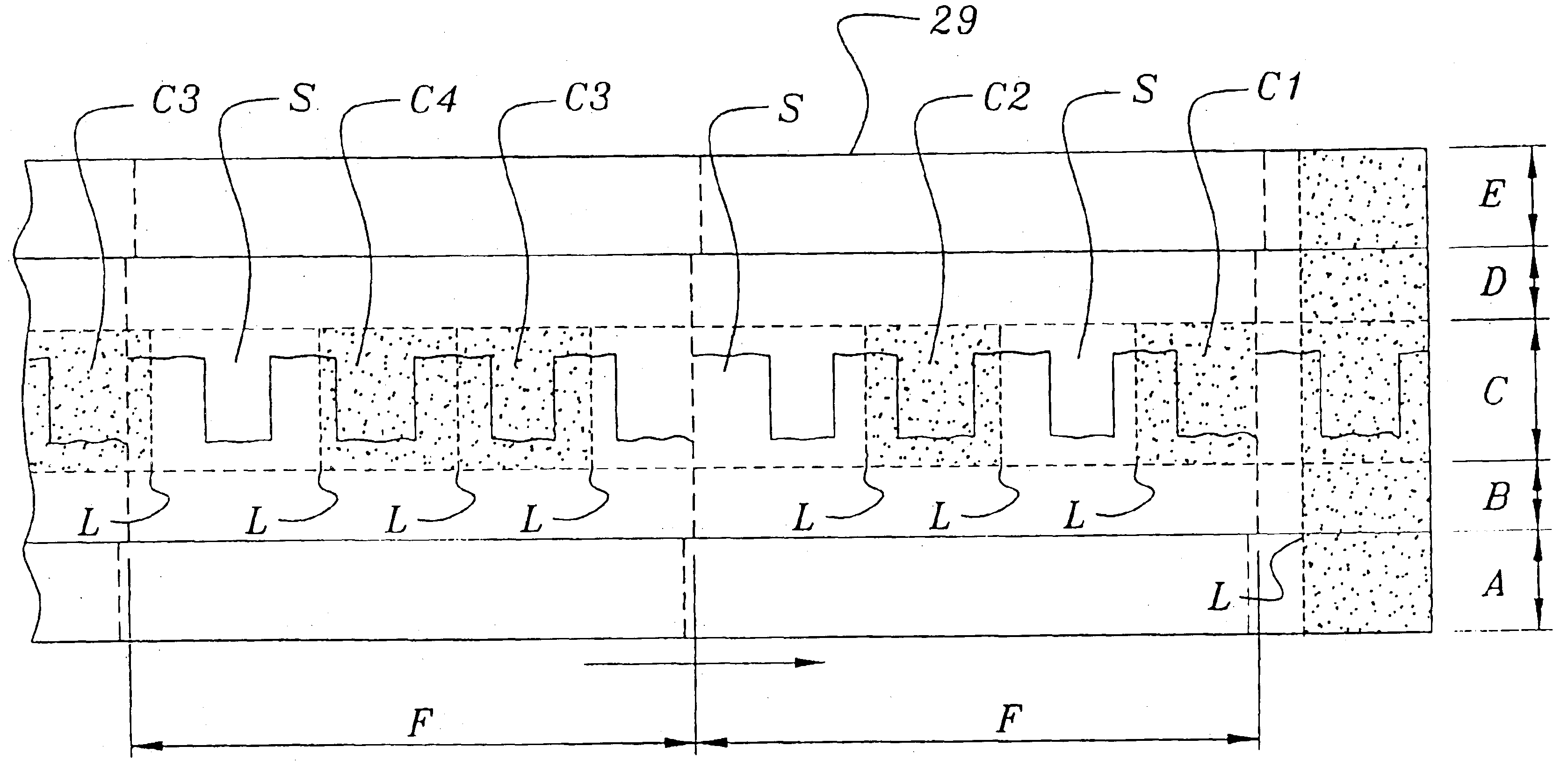
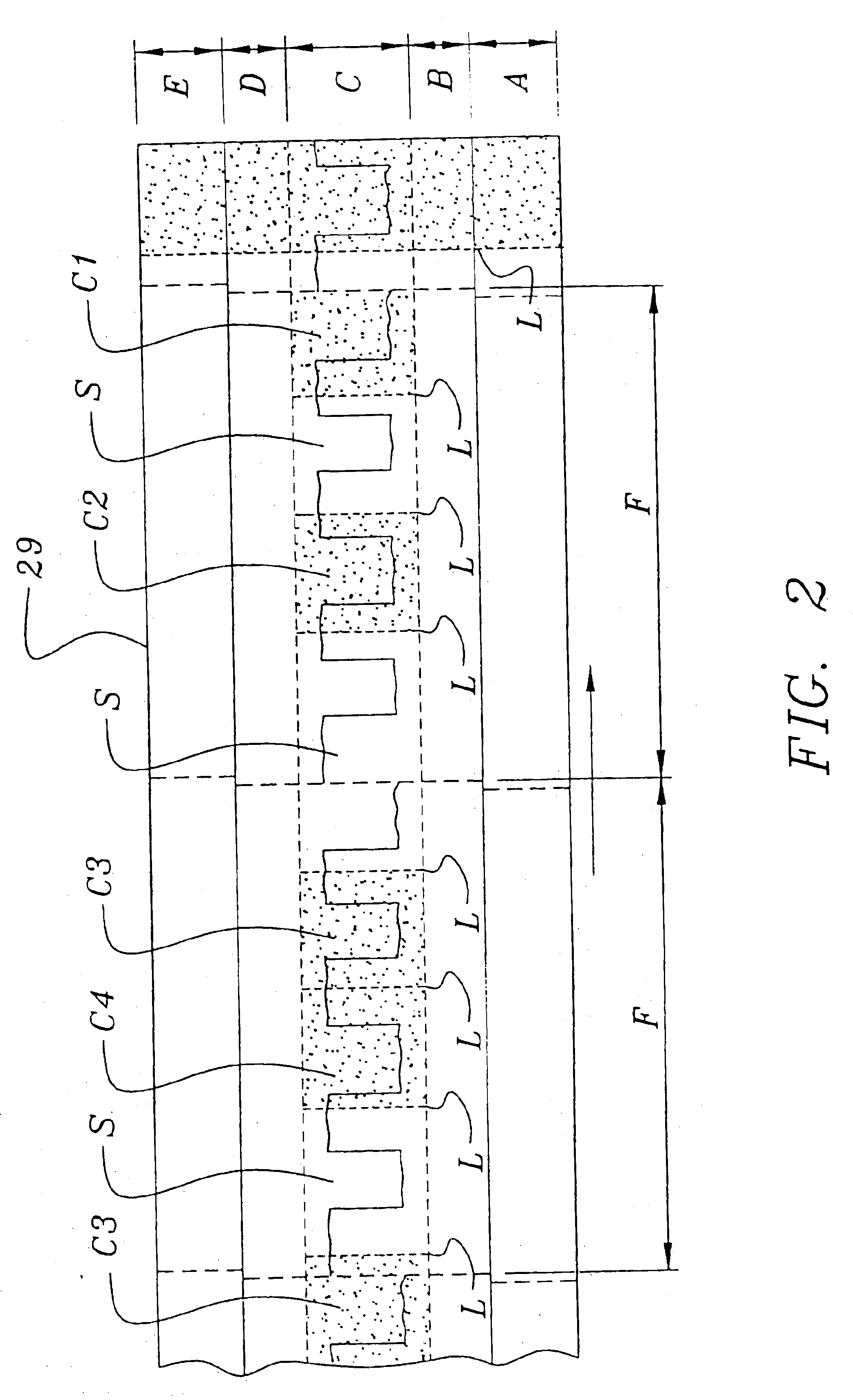
[0021]A third cut is made (i) alternately across and generally along the centerline of the tri-level section (i.e., multi-layered portion) formed by the two previous laminations and (ii) within the longitudinal side boundaries of this section. This central cut, which divides the sheet into two elongate parts, is made to form a repeating pattern of interdigitating triply thick tabs so that upon separation each part has a long straight edge along one side which is one layer in thickness and alternating triply layered tabs and cut-out portions along the other side. Each of the narrow strips, which were positioned to underlie the uppermost wider strip, is desirably cut to be wide enough to completely cover the underside of the wider strip's tabs, but not so wide as to extend much toward the long straight edge of the wider strip. The width is desirably sufficient to adequately support the overlying shingle portion and to contribute to ease of production in the continuous manufacturing process. The two elongate laminated sheets are finally cut into suitable lengths for shingles and packaged. This final cutting may be accomplished conveniently just about when the third longitudinal cut is made or thereafter.

Problems solved by technology

While the resultant bilaminate structure suggests somewhat the substantial and imposing architectural appearance of the more expensive roofing materials, such as wood shingles, the structure still diverges considerably in appearance from them.

Method used


Image

  • Multi-layered shingle and method of making same
  • Multi-layered shingle and method of making same
  • Multi-layered shingle and method of making same

Examples


Embodiment Construction

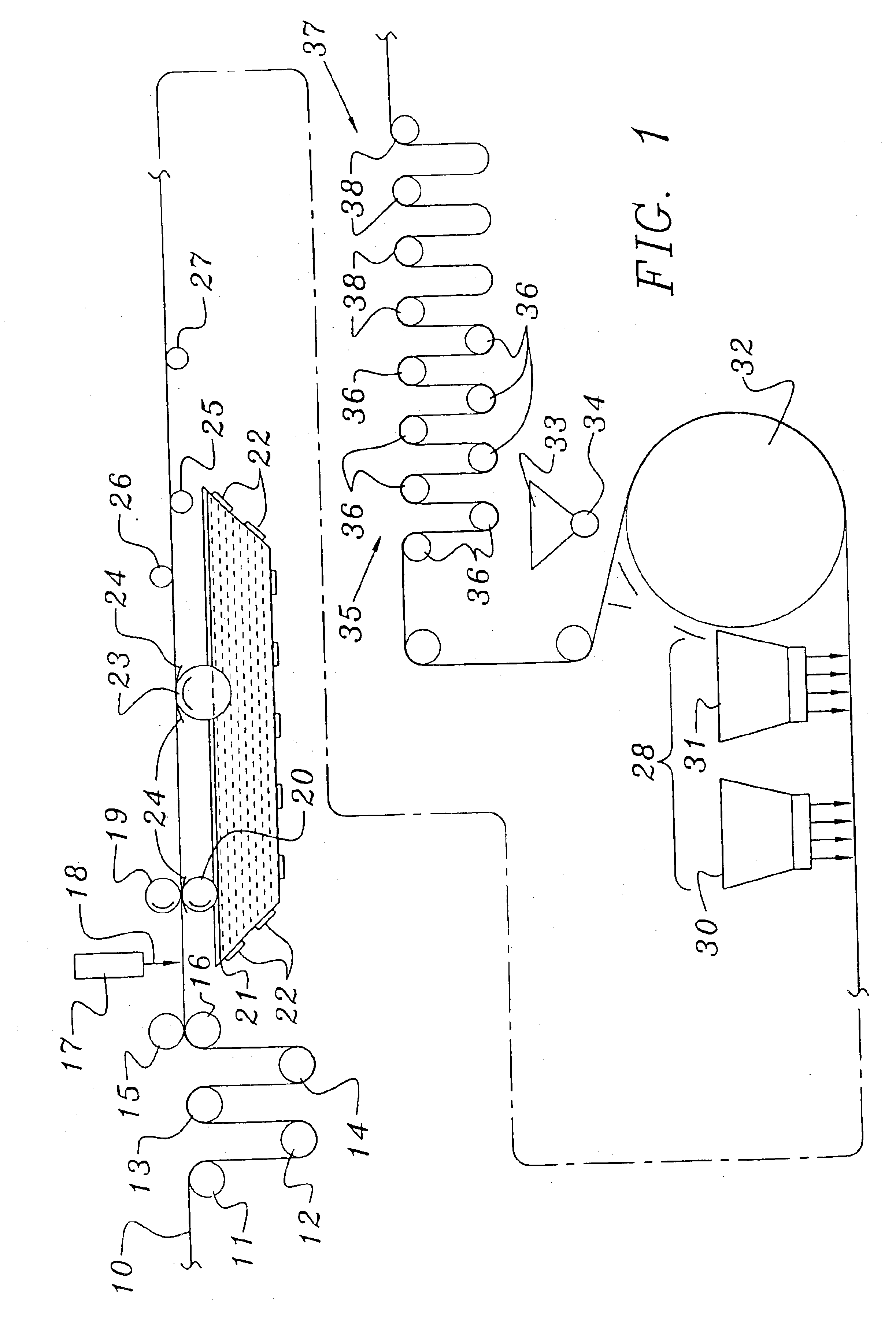
[0029]Referring now to the drawings and more specifically to FIGS. 1 and 3 thereof, there is shown diagrammatically an overall process for forming multi-layered roofing shingles according to the instant invention. A rectangular sheet or web 10 of an indefinite length is unwound from a roll (not shown) and fed along the production line. Sheet 10 is preferably a mat of glass fibers but may also be fabricated from organic felt or other types of base material. The glass mat is generally about 38 to 48 inches in width, although other widths can be chosen without departing from the scope of the invention. The sheet generally weighs from about 1.35 to 3.00 lbs / 100 ft.2

[0030]After sheet 10 is fed over a series of loopers 11-14 and between a pair of tension rollers 15 and 16 for uniform tensioning, it is then passed to a station for the application of filled asphalt coating. Discharge pipe 17 supplies a layer of the asphalt coating 18 to the upper surface of sheet 10 just before the nip of ...


PUM

PropertyMeasurementUnit
Lengthaaaaaaaaaa

Abstract

A multi-layered shingle adapted to be positioned with other similar shingles in an overlapping arrangement on a roof to yield a simulated wooden shake roof covering comprising a headlap portion and a butt portion. The butt portion comprises a series of multi-layered tabs. All the tabs have the same number of layers and each multi-layered tab (a) is separated from the next adjacent multi-layered tab or tabs by a space or spaces, respectively, and (b) comprises an uppermost layer and at least two layers underlying the uppermost layer. Each underlying layer is laminated to the layer above it to form a multi-layered laminated composite. The laminated composite is integral with the headlap portion and the top surface of the uppermost layer of each tab is coplanar with the top surface of the headlap portion. The invention also includes an apparatus and a process for the continuous manufacture of the shingles of the invention.

Description

CROSS-REFERENCE TO RELATED APPLICATIONS[0001]This is a continuation application of U.S. application Ser. No. 09 / 994,393 filed Nov. 26, 2001 now U.S. Pat. No. 6,679,020, which in turn is a divisional of U.S. application Ser. No. 09 / 303,840 filed May 3, 1999, now U.S. Pat. No. 6,355,132.BACKGROUND OF THE INVENTION[0002]1. Field of the Invention[0003]This invention relates to a method for making multi-layered shingles, and to roofing shingles made thereby. The shingles are uniquely thickened to enhance the appearance of a roof.[0004]2. Description of the Prior Art[0005]There have been many approaches by the roofing industry to the task of covering a roof deck with shingles which are both protective and aesthetically pleasing. Whatever their appearance, suitable shingles have been made sufficiently durable and weatherproof for prolonged protection of the roof. The shingles' visual appeal has been attained in various ways, such as by providing particular butt edge contours and surface tr...

Claims


Application Information

Patent Timeline
IPC IPC(8): E04D1/00E04D1/26B32B37/00
CPCB32B38/1808E04D1/26Y10T156/1322B32B2038/045B32B2305/30B32B2307/404B32B2395/00E04D2001/005Y10T156/1069Y10T428/2438Y10T156/1087Y10T156/1085Y10T428/24355Y10T156/1075Y10T156/1343Y10T156/1326Y10T156/1084Y10T156/13B32B38/1875
Inventor BECKER, WALTER F.ROOKS, KEITH A.FREEMAN, SHELBY L.
Owner CERTAINTEED CORP
Learn More