Pneumatic tire with sidewall projections

a pneumatic tire and sidewall technology, applied in the field of pneumatic tires, can solve the problems of not providing the desired traction, affecting the performance of the tire, and being more susceptible to puncture, so as to reduce the collection of materials and increase the traction

Inactive Publication Date: 2005-07-26
BRIDGESTONE AMERICAS TIRE OPERATIONS LLC
View PDF27 Cites 44 Cited by
  • Summary
  • Abstract
  • Description
  • Claims
  • Application Information

AI Technical Summary

Benefits of technology

[0013]Another feature of the invention is providing each lug group with three individual lugs each having outwardly tapered side and bottom surfaces which reduce the accumulation of debris therebetween and which provide a plurality of spaced edges at various distances from the sidewall for increased traction in dry ruts as well as in soft soil conditions.
[0014]Another aspect of the invention is that the three lugs of the repeating lug groups provides three different levels along the sidewall which reduces the collection of materials by providing discontinuous surfaces along the sidewall and which provide the tire with the ability to gain forward traction in deep ruts to pull the vehicle forward.

Problems solved by technology

Although these tires and their tread patterns may provide increased traction in soft sand and similar soil, some of them are limited almost entirely to off-road use and would not perform satisfactorily on a paved road.
Likewise, some of these tires do not provide the desired traction, especially in extremely deep ruts, to enable the tire to dig itself out from extremely soft and muddy conditions while providing the desired amount of debris deflection and reduced accumulation of mud and rocks in the sidewall area, which area is more susceptible to puncture than the ground engaging tread area of the tire.

Method used


Image

  • Pneumatic tire with sidewall projections
  • Pneumatic tire with sidewall projections
  • Pneumatic tire with sidewall projections

Examples


embodiment 1

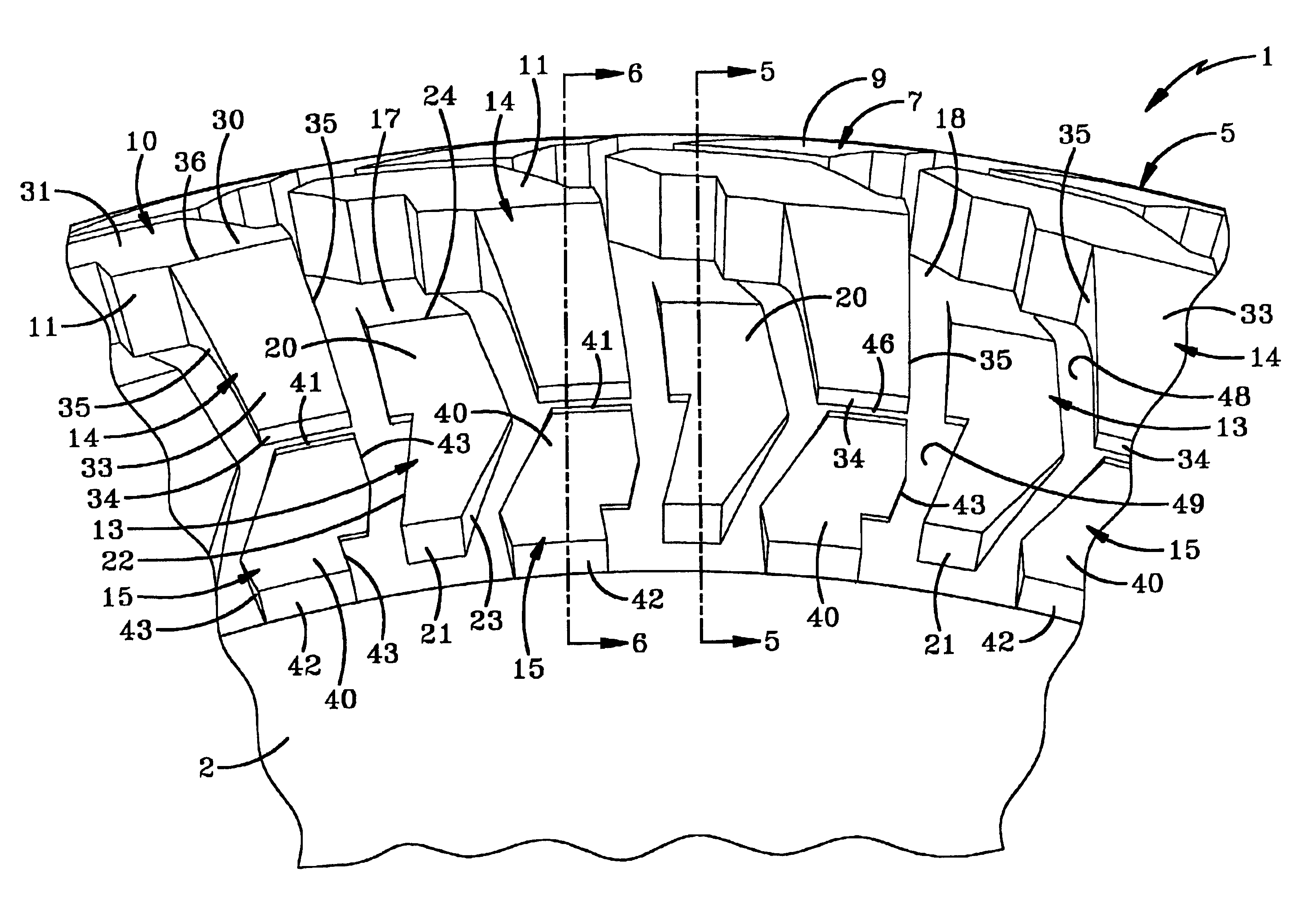
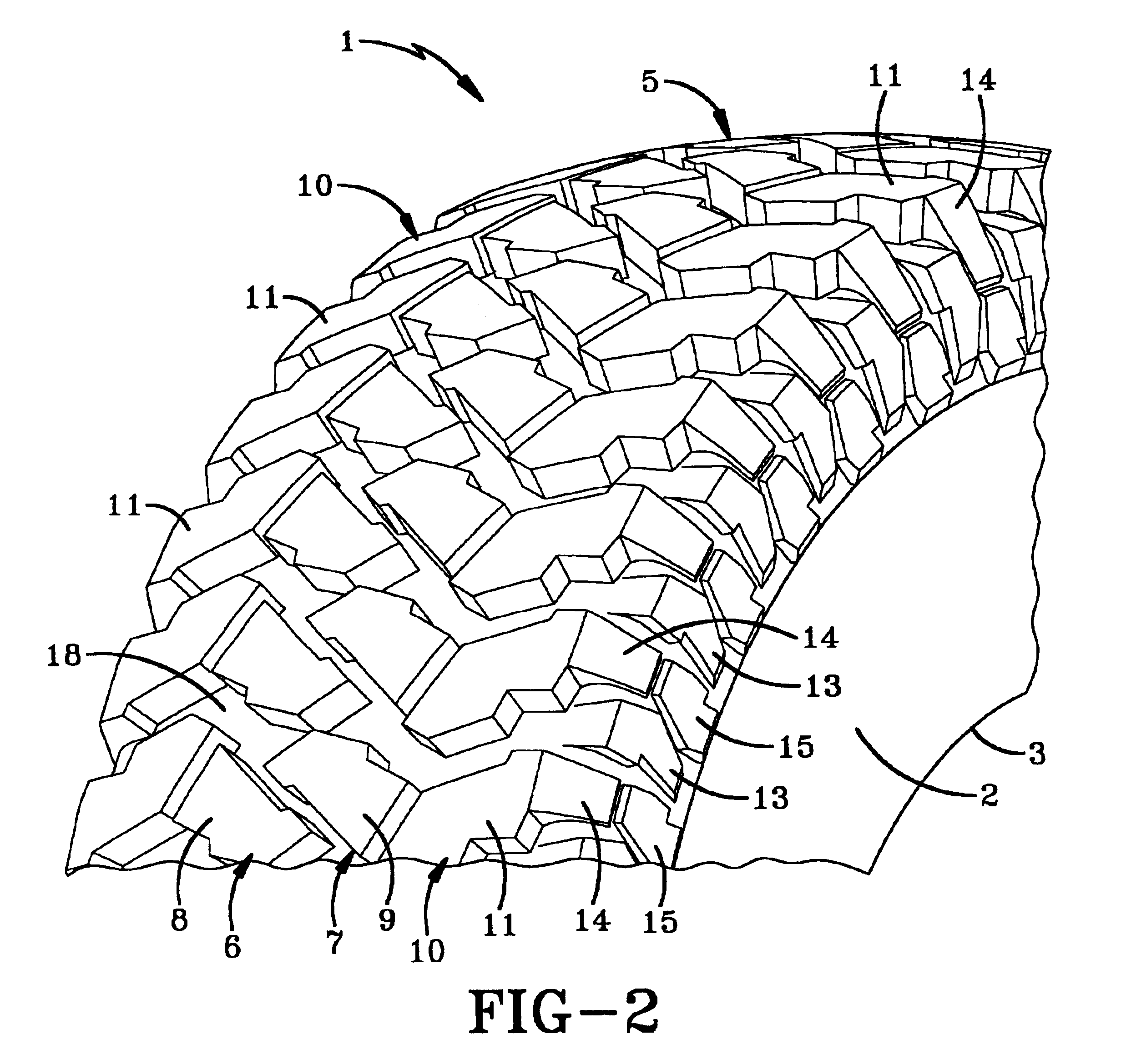
[0038]As shown in FIG. 12, sidewall projections are formed by repeating lug groups, each preferably including three individual lugs indicated at 58, 59, and 60 which correspond to lugs 13, 14, and 15 respectively, of embodiment 1. As shown by comparison of FIGS. 4 and 12, lugs 58-60 have different geometric configurations than lugs 13-15. However, in accordance with the invention, the cross sectional configurations thereof as shown in FIGS. 5 and 6, are the same for the lugs of embodiments 1 and 50 even though the geometrical configurations or shape thereof are different. Again, the important features are that generally flat outer surface 62 of first lug 58 has a top surface 63 which aligns with and lies generally in the same plane as inner tread surface 18. Likewise, top surface 65 of second lug 59 merges into and lies in the same general plane as ground engaging surface 65 of adjacent shoulder rib lug 56. Also, third lug 60 is radially aligned with second lug 59 and has a generall...

embodiment 90

[0040]A fourth pneumatic tire embodiment is shown in FIG. 14 and is indicated generally at 90. Embodiment 90 again has the circumferentially spaced lug groupings with the three individual lug elements being indicated at 91, 92, and 93, which correspond to lug elements 13-15, 58-60, and 76-78. Top surface 95 of first lug 91 aligns with inner tread surface 18 and top surface 96 of second lug 92 merges into and aligns with top road engaging surface 97 of shoulder rib 98.

[0041]FIG. 7 shows the general position of the lugs for the various tire tread embodiments when the tire is on a generally flat level surface 102, and FIG. 8 shows the various tire embodiments when in an extremely soft soil 105. When in soil 105 the sidewall projections or lugs actually will engage the sidewalls 103 of a rut 104 to dig or raise the tire out of the bottom of the rut to prevent the tire from being stuck or freely spinning in the rut.

[0042]Tests have shown that the unique arrangement of the sidewall lugs e...


PUM


Abstract

A pneumatic tire has an aggressive tread pattern for use on both on-road and off-road vehicles having at least a pair of intermediate ribs and a pair of shoulder ribs providing the ground engaging tread lugs. A plurality of circumferentially extending lug groups are formed on and extend outwardly from and along the sidewalls of the tire. Each lug group preferably includes three separate lugs, each lug having a substantially flat outer surface lying in a different plane than the outer surfaces of the other two lugs. Two of the lugs are radially aligned with each other along the sidewall of the tire with the third lug lying intermediate spaced pairs of these aligned lugs. The lugs are formed with sharp corners offset from each other which extend outwardly from the sidewall to different levels. A top surface of one of the lugs aligns with the ground engaging surface of an adjacent shoulder rib tread lug and the top surface of the intermediate lug aligns with the inner tread surface of the road engaging tread pattern.

Description

CROSS REFERENCE TO RELATED APPLICATION[0001]This application claims the benefit of provisional application Ser. No. 60 / 316,623, filed Aug. 31, 2001.BACKGROUND OF THE INVENTION[0002]1. Technical Field[0003]The invention relates to pneumatic tires and more particularly to a pneumatic tire for both off-road and on-road usage having sidewall projections which deflect debris away from the sidewalls to prevent sidewall penetration and which provides increased traction for soft or compact soil conditions when used off-road.[0004]2. Background Information[0005]Numerous pneumatic tires have been designed with aggressive tread patterns for use both on-road and off-road which have various sidewall projections to prevent the accumulation of dirt and debris in the sidewalls when used off-road. These projections also reduce sidewall penetration and provide increased traction in various soil conditions such as mud, sand, gravel, etc. and in extremely rocky conditions.[0006]Many of these prior trea...

Claims


Application Information

Patent Timeline
Patent Type & Authority Patents(United States)
IPC IPC(8): B60C11/01B60C11/11
CPCB60C11/01B60C11/0316B60C2200/14Y10S152/902
Inventor ALLISON, WILLIAM B.GUSPODIN, JAMES G.REEP, DAVID M.YOUNG, JOHN E.
Owner BRIDGESTONE AMERICAS TIRE OPERATIONS LLC
Why Eureka
Try Eureka