Method and system for facilitating horizontal drilling

a technology of horizontal drilling and lateral wellbore, which is applied in the direction of drilling pipes, directional drilling, borehole/well accessories, etc., can solve the problems of limited hydrocarbon production rate and insufficient recovery of wellbores in subterranean formations, and achieve the effect of facilitating horizontal drilling of such lateral wellbores through well casings and reducing power requirements

Inactive Publication Date: 2005-07-26
V2H INT PTY LTD ABN 37 610 667 037
View PDF26 Cites 83 Cited by
  • Summary
  • Abstract
  • Description
  • Claims
  • Application Information

AI Technical Summary

Benefits of technology

[0005]According to the present invention, lateral (i.e., horizontal) wellbores are utilized to facilitate a more efficient sweep in secondary and tertiary hydrocarbon recovery fields, and to reduce the power required to inject fluids and dispose of waste materials into wells. The horizontal drilling of such lateral wellbores through a well casing is facilitated by positioning in the well casing a shoe defining a passageway extending from an upper opening in the shoe through the shoe to a side opening in the shoe. A rod and casing mill assembly is then inserted into the well casing and through the passageway in the shoe until a casing mill end of the casing mill assembly abuts the well casing. The rod and casing mill assembly are then rotated until the casing mill end forms a perforation in the well casing.

Problems solved by technology

The rate at which hydrocarbons are produced from wellbores in subterranean formations is often limited by wellbore damage caused by drilling, cementing, stimulating, and producing.
As a result, the hydrocarbon drainage area of wellbores is often limited, and hydrocarbon reserves become uneconomical to produce sooner than they would have otherwise, and are therefore not fully recovered.

Method used


Image

  • Method and system for facilitating horizontal drilling
  • Method and system for facilitating horizontal drilling
  • Method and system for facilitating horizontal drilling

Examples


Embodiment Construction

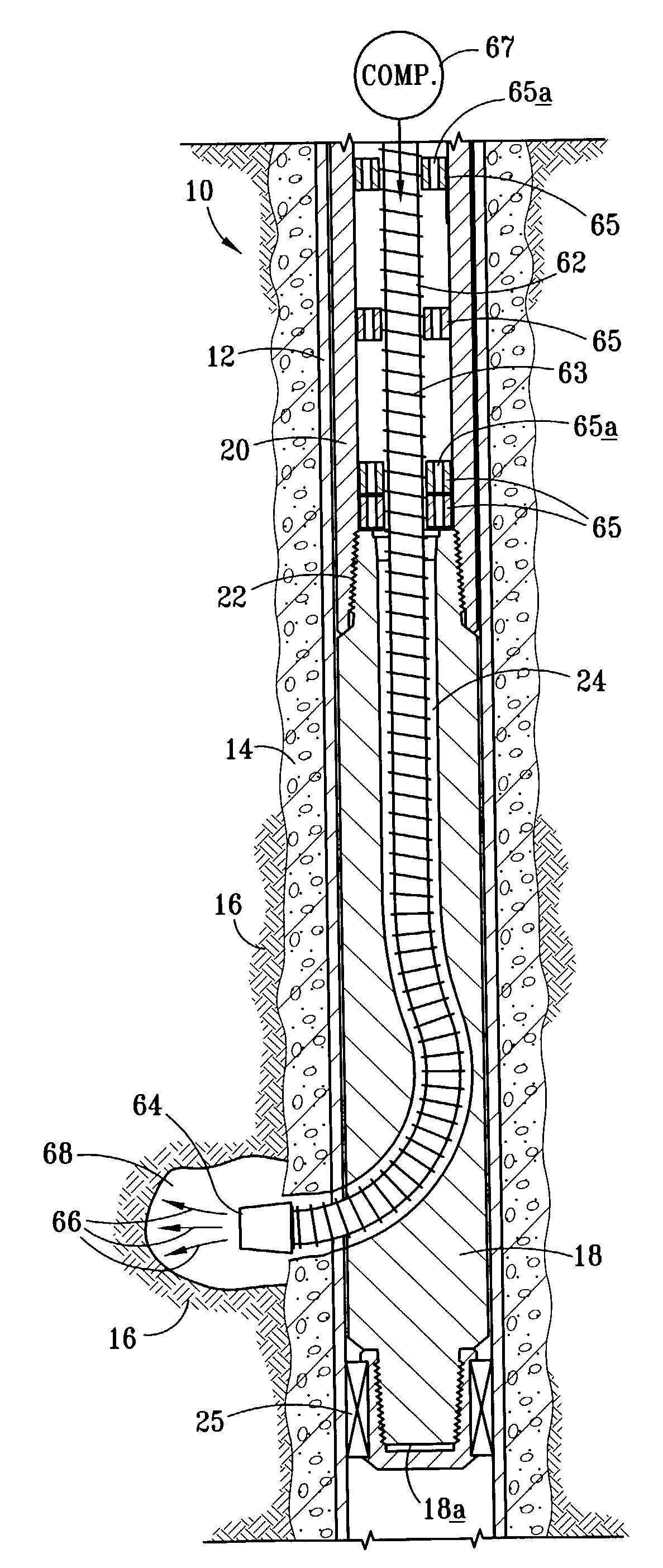
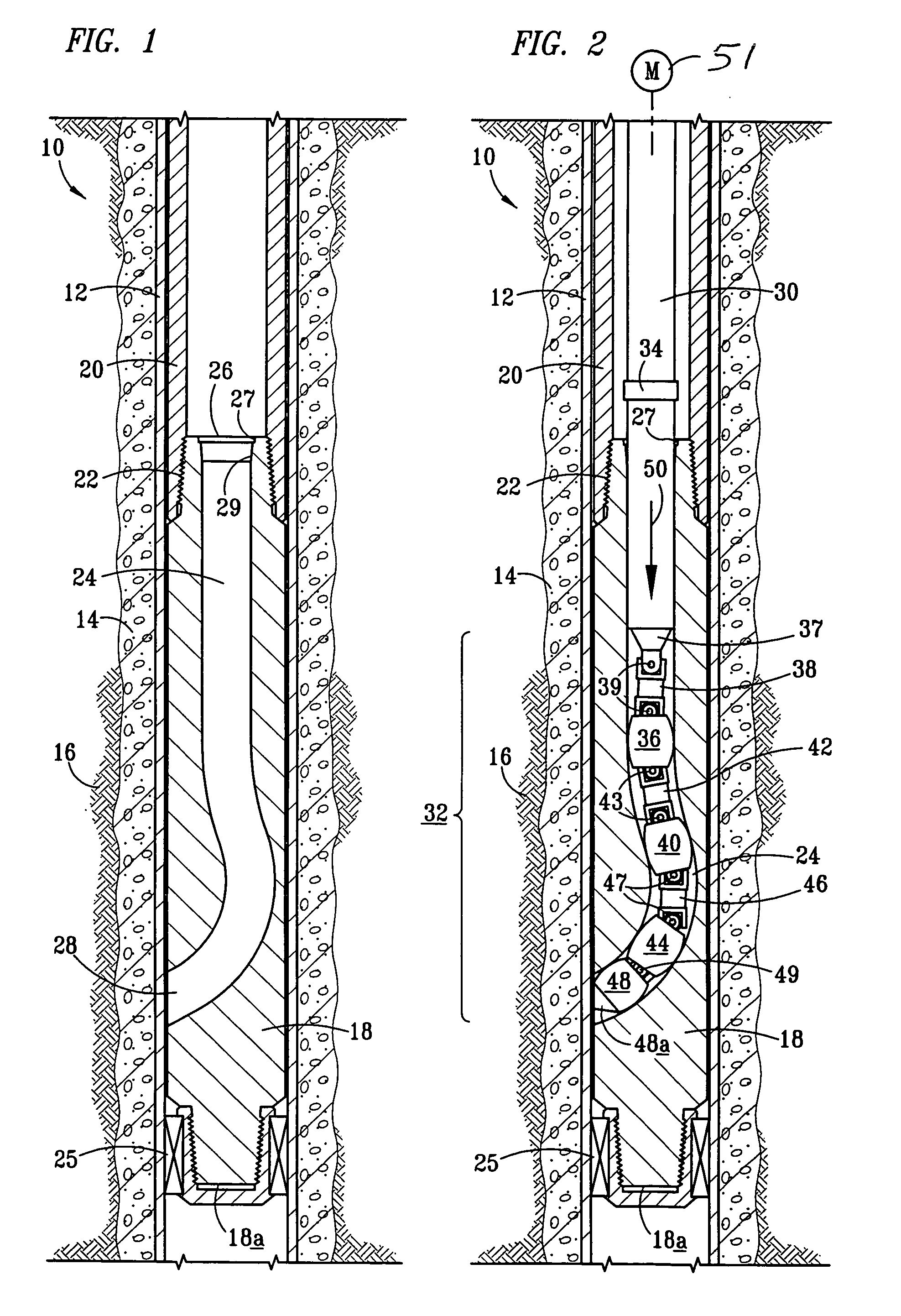
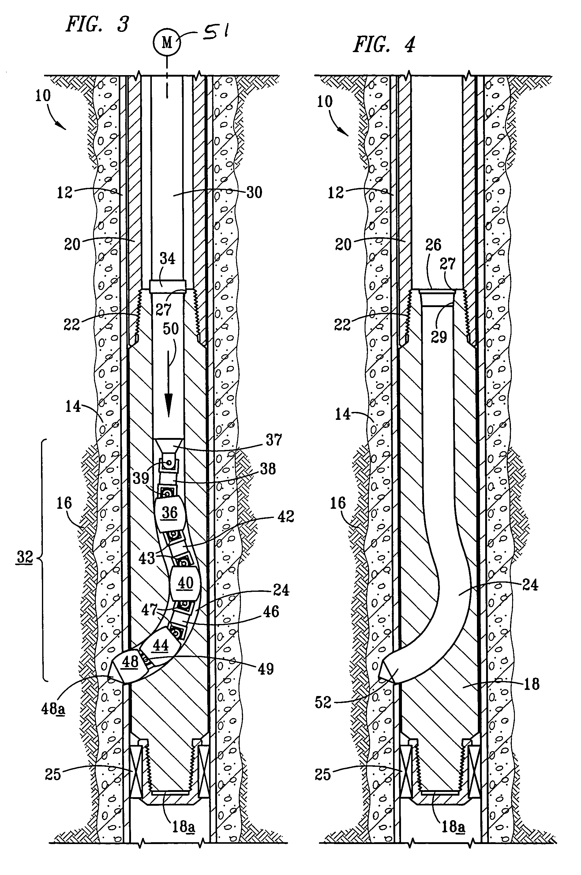
[0014]In the discussion of the FIGURES the same reference numerals will be used throughout to refer to the same or similar components. In the interest of conciseness, various other components known to the art, such as wellheads, drilling components, motors, and the like necessary for the operation of the wells, have not been shown or discussed except insofar as necessary to describe the present invention.

[0015]Referring to FIG. 1 of the drawings, the reference numeral 10 generally designates an existing well 10 encased by a well casing 12 and cement 14. The well 10 passes through a subterranean formation 16 from which petroleum is drawn. A drilling shoe 18 is securely attached to a tubing 20 via a tapered threaded fitting 22 formed between the tubing 20 and the shoe 18. The shoe 18 and tubing 20 are defined by an outside diameter approximately equal to the inside diameter of the well casing 12 less sufficient margin to preclude jamming of the shoe 18 and tubing 20 as they are lowere...


PUM


Abstract

A method for facilitating horizontal drilling by positioning in a well casing a shoe defining a passageway extending from an upper opening in the shoe through the shoe to a side opening in the shoe. A rod is connected, through at least one block and pin assembly operative as a universal joint, to a casing mill end, and inserted into the well casing and through the passageway in the shoe until the casing mill end substantially abuts the well casing. The rod and casing mill end are then rotated until the casing mill end substantially forms a perforation in the well casing. The rod and casing mill end are then withdrawn from the well casing, and a nozzle attached to the end of a flexible hose is extended through the passageway to the perforation. Fluid is then ejected from the nozzle and impinges and erodes subterranean formation material.

Description

CLAIM OF PRIORITY[0001]This application claims priority from U.S. Provisional Patent Application No. 60 / 348,476 entitled “METHOD AND SYSTEM FOR FACILITATING HORIZONTAL DRILLING” filed on behalf of Belew, et al, on Nov. 7, 2001.TECHNICAL FIELD[0002]The present invention relates generally to a method and system for facilitating horizontal drilling into a subterranean formation surrounding a well casing.BACKGROUND[0003]The rate at which hydrocarbons are produced from wellbores in subterranean formations is often limited by wellbore damage caused by drilling, cementing, stimulating, and producing. As a result, the hydrocarbon drainage area of wellbores is often limited, and hydrocarbon reserves become uneconomical to produce sooner than they would have otherwise, and are therefore not fully recovered. Similarly, increased power is required to inject fluids, such as water and CO2, and to dispose of waste materials, into wellbores when a wellbore is damaged.[0004]Accordingly, there is a n...

Claims


Application Information

Patent Timeline
Patent Type & Authority Patents(United States)
IPC IPC(8): E21B7/04E21B7/06E21B7/18
CPCE21B7/061E21B7/18
Inventor BELEW, DAVID A.BELEW, BARRY
Owner V2H INT PTY LTD ABN 37 610 667 037
Why Eureka
Try Eureka