

Seat for car
- Summary
- Abstract
- Description
- Claims
- Application Information
AI Technical Summary
Benefits of technology
Problems solved by technology
Method used
Image

Examples
first embodiment
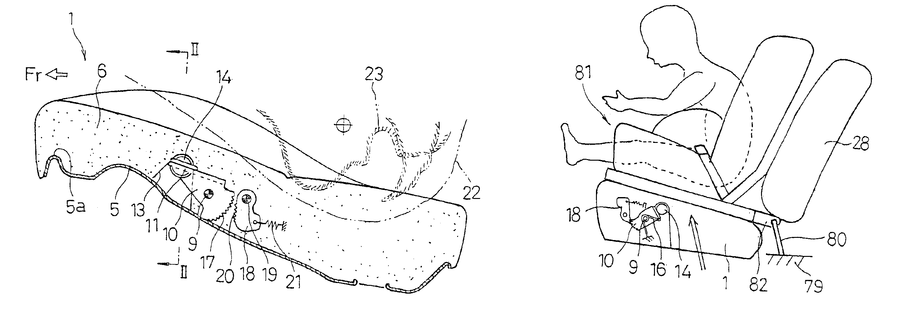
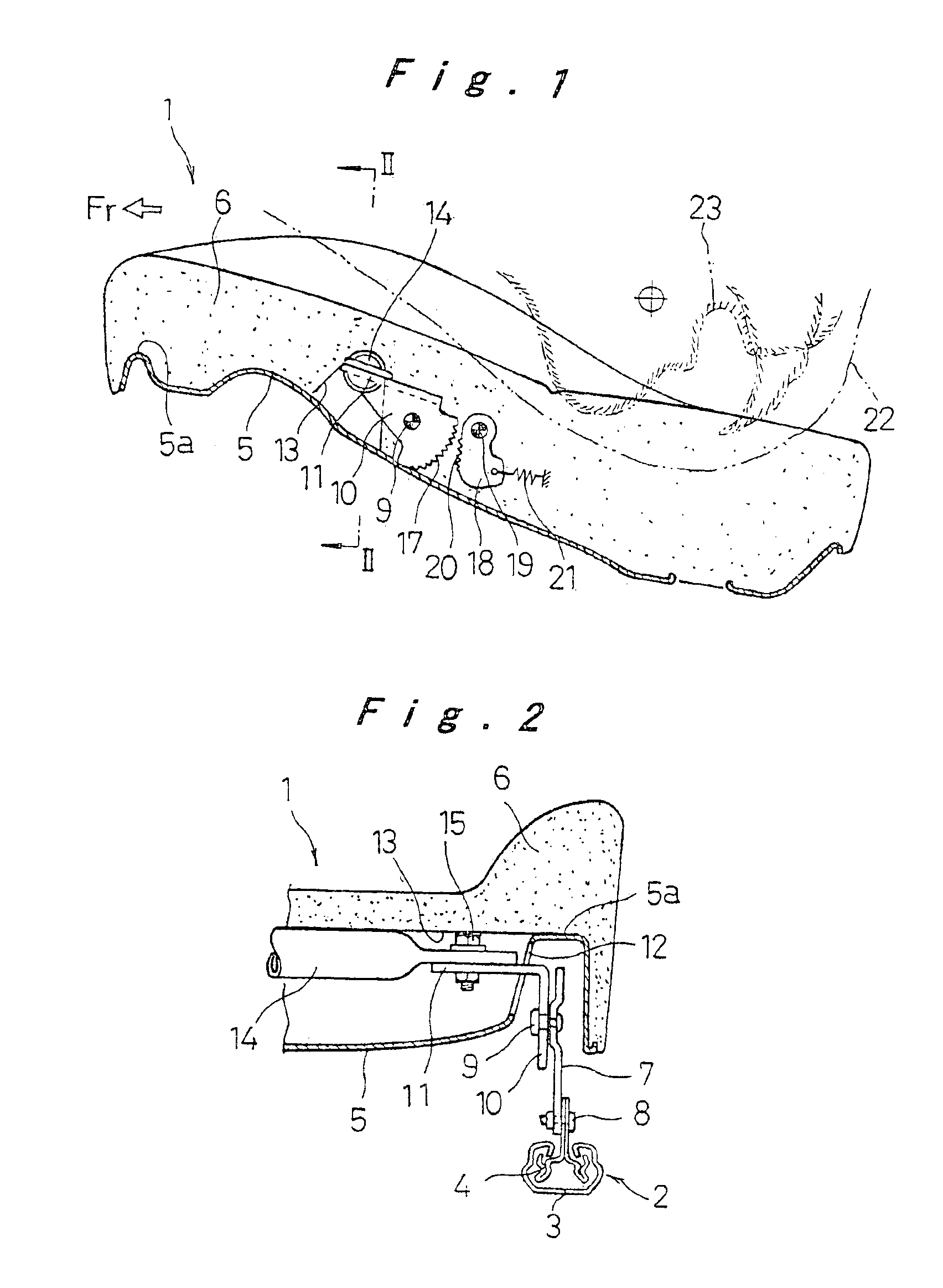
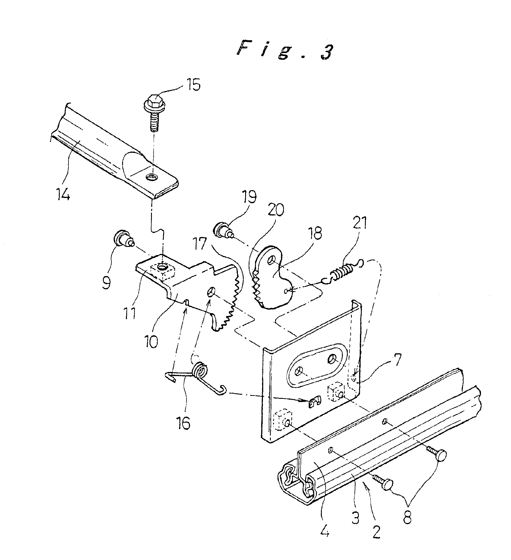
[0068]Hereinafter, the car seat of the present invention will be described with reference to FIGS. 1 to 5.
[0069]In FIGS. 1 to 3, 1 designates a seat cushion of the car seat, which is attached onto a floor so as to be adjustable in position back and forth by means of seat rails 2 on both right and left sides. The seat rails 2 each have an upper rail 4 which is mounted on a lower rail 3 so as to be slidable and fixable in an arbitrary position, the lower rail 3 being fixed to the floor of the car body. Designated by 5 is a steel-plate frame unit of the seat cushion 1, which is mounted on the upper rails 4 of the right and left seat rails 2 at both sides of its bottom. A cushion pad 6 made of urethane foam or the like is mounted on the top of this frame unit 5. The external surface is further covered with an exterior member (not shown). A peripheral bank part 5a bulged upward is arranged on the outer periphery of the frame unit 5. The cushion pad 6 is formed to fit to the inner and out...
second embodiment
[0080]Now, the car seat of the present invention will be described with reference to FIGS. 6 to 8. Incidentally, in the description of the following embodiments, the same components as in the preceding embodiment(s) will be designated by identical reference numerals and description thereof will be omitted. Description will be given of differences alone.
[0081]In the present embodiment, the frame unit 5 is supported by the support brackets 7. These support brackets 7 are each provided with a pair of holding plates 24a and 24b for swingably sandwiching and holding a swing arm 10 and a pendulum member 18 which constitute the catch part, with spacers 24c interposed therebetween. In FIG. 8, designated by 5b and 5c are fixing bolts and nuts for fastening and fixing the frame unit 5 to the supporting brackets 7. The pair of holding plates 24a and 24b are fastened and fixed to a support bracket 7 with three pins, or a spindle pin 9, a pivotal support pin 19, and an mounting pin 25 which are ...
third embodiment
[0088]Now, the car seat of the present invention will be described with reference to FIGS. 10 to 12.
[0089]In the present embodiment, an auxiliary plate 31 is arranged as auxiliary means in a position behind the catch member 14 of the car seat having the configuration shown in FIG. 9. The auxiliary plate 31 has support tabs 31a extended down from both sides of its center portion in the front-to-back direction. The auxiliary plate 31 is vertically swingably supported via pivotal support pins 32 on pivotal support brackets 33 which are fixed onto the frame unit 5. The front end of the auxiliary plate 31 is provided with a push-up engaging part 34 which comes into engagement with and push up the lower end of the catch member 14. There are also provided a stopper 35 for controlling the lower end of swing of this push-up engaging part 34 and extension springs 36 for urging downward swing. The auxiliary plate 31 is arranged inside an auxiliary plate layout recess 37 which is made in the cu...
PUM
 Abstract
Description
Claims
Application Information