Flashlight with heat-dissipation device

a technology of heat dissipation device and flashlight structure, which is applied in the direction of semiconductor devices for light sources, lighting and heating apparatus, and light support devices. it can solve the problems of high-power leds that would produce a lot of heat, reduce the usefulness of leds, and heat dissipation problems in applications, so as to reduce the breakdown rate of flashlight structure and increase the use life of high-power luminaries.

Inactive Publication Date: 2005-07-26
YEN MEI FENG
View PDF2 Cites 101 Cited by
  • Summary
  • Abstract
  • Description
  • Claims
  • Application Information

AI Technical Summary

Benefits of technology

[0008]It is an object of the present invention to provide a flashlight structure with a heat-dissipating device, which prevents from heat accumulation, thereby decreasing the breakdown rate of the flashlight structure and increasing the use life of the high-power luminary.
[0019]In accordance with another aspect of the present invention, the flashlight structure includes a base having a conducting point isolated with the base; a high-power luminary disposed on the base and having an anode electrode connecting with the conducting point and a cathode electrode connecting with the base; a power source having a positive terminal connecting to the conducting point and a negative terminal connecting to the base for providing the luminary with power; and a housing including the base and having plural heat sink for dissipating heat produced by the high-power luminary, thereby preventing the high-power luminary of the flashlight structure from damage or diminution of use life.
[0025]In accordance with another aspect of the present invention, the housing structure for a flashlight having a high-power luminary, includes plural heat sink for dissipating heat produced by the high-power luminary, thereby preventing the high-power luminary of the flashlight structure from damage or diminution of use life.

Problems solved by technology

Unfortunately, a high-power LED would produce a lot of heat, and that will be a serious problem to limit its usefulness.
The prior high-power LED flashlight structures are easy to be operated and assembled, but they cause the heat-dissipating problem in application.
Usually, the LED will transform 10% electricity into light and 90% electricity into heat, but the prior art can't remove the heat produced by the luminary efficiently, thereby the use life of the flashlight is decreased.

Method used


Image

  • Flashlight with heat-dissipation device
  • Flashlight with heat-dissipation device
  • Flashlight with heat-dissipation device

Examples


Embodiment Construction

[0032]The present invention discloses a high-power flashlight structure with a heat-dissipating device, and the objects and advantages of the present invention will become more readily apparent to those ordinarily skilled in the art after reviewing the following detailed description. The present invention needs not be limited to the following embodiment. It can be applied in a high-power LED luminary or other high-power luminaries etc.

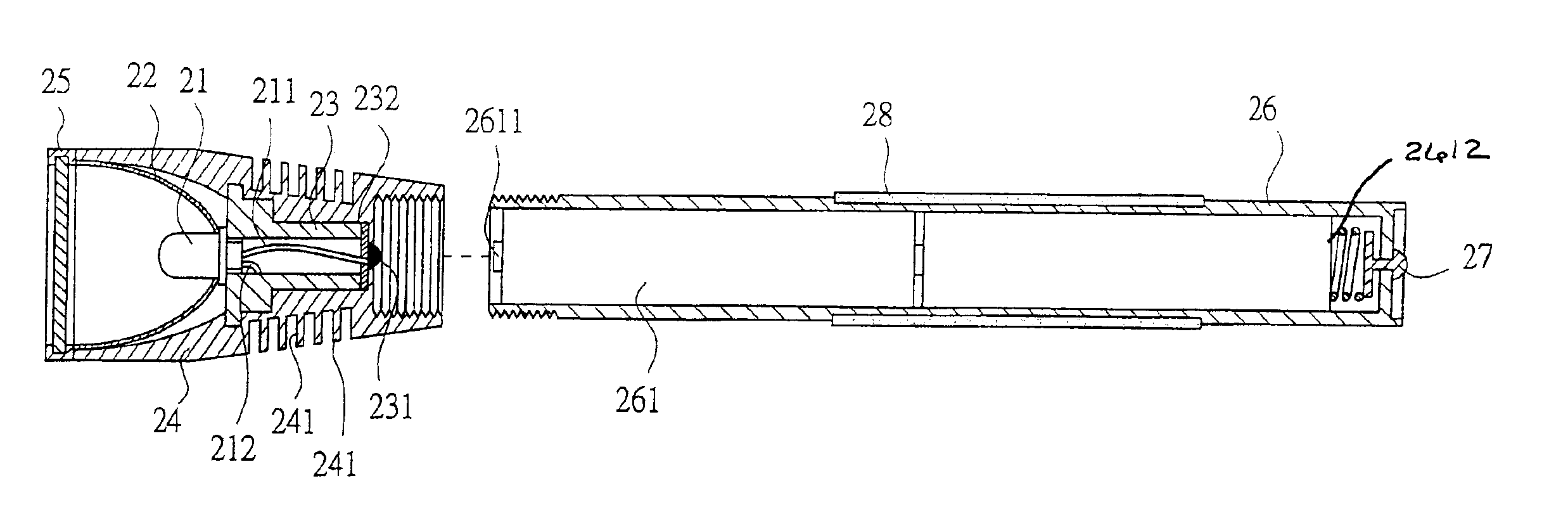
[0033]Please refer to FIG. 3 showing a cross-section structure of a high-power LED flashlight according to the present invention according to a preferred embodiment of the present invention. As being shown in FIG. 3, the flashlight structure includes a base 23 having a conducting point 231 isolated with the base via an isolating piece 232; a high-power luminary 21 disposed on the base 23 and having an anode 211 electrode connecting with the conducting point 231 and a cathode electrode 212 connecting with the base; a power source 261 of a casing having ...


PUM


Abstract

A flashlight structure with a heat-dissipation device is disclosed. The flashlight structure includes a base having a conducting point isolated with the base; a high-power luminary disposed on the base and having an anode electrode connecting with the conducting point and a cathode electrode connecting with the base; a power source having a positive terminal connecting to the conducting point and a negative terminal connecting to the base for providing the luminary with power; and a housing including the base and having plural heat sink for dissipating the heat produced by the high-power luminary, thereby preventing the flashlight from damage of device or diminution of use life.

Description

BACKGROUND OF THE INVENTION[0001](a) Field of the Invention[0002]This invention relates to a flashlight structure, and more particularly to a flashlight structure with a heat-dissipation device.[0003](b) Description of the Prior Art[0004]Flashlights are extremely useful as portable lighting devices. There are several types of the flashlights provided according to the requirement, wherein a flashlight with a high-power luminary is one of those developed directions. On the other hand, a light emitting diode (LED) is well considered as a luminary. Being compared with the conventional luminary, for example a pilot lamp, fluorescent lamps, an incandescent lamp and so on, the LED has several features of small volume, low heat-produced, low power consumption, long use life, high responding speed, environmental-protection, thin and compact. However, LED flashlight always has to include a LED array to put in use. Recently, high-power LED is developed and well down. Therefore, a high-power LE...

Claims


Application Information

Patent Timeline
Patent Type & Authority Patents(United States)
IPC IPC(8): F21V29/00F21L4/00F21L4/02
CPCF21L4/027F21V29/004F21V29/89F21V29/75F21V29/767F21Y2101/02F21Y2115/10F21V29/70
Inventor YEN, MEI-FENG
Owner YEN MEI FENG
Why Eureka
Try Eureka