Connector having shielding shell

a shielding shell and connector technology, applied in the direction of coupling device connection, multi-conductor cable end pieces, coupling protective earth/shielding arrangement, etc., can solve the problem of deteriorating the reliability of contact between the shielding shell and the shielding casing, the elastic bending state of the sealing member is not uniform in the circumferential direction, and the close contact state of the sealing member with the outer circumference of the housing and the inner circumference of the mounting hole is no

Inactive Publication Date: 2005-07-26
AUTONETWORKS TECH LTD +2
View PDF5 Cites 62 Cited by
  • Summary
  • Abstract
  • Description
  • Claims
  • Application Information

AI Technical Summary

Benefits of technology

[0015]It is therefore an object of the invention to provide an equipment shield connecter ha

Problems solved by technology

Thus, the reliability of contact between the shielding shell and the shielding casing may be deteriorated.
However, it may be considered that the equipment-side terminals are obliged to be disposed alongside due to some restriction caused by the layout of the equipment or other peripheral parts.
However, in the case where the outer circumference of the housing and the sealing member are formed into a noncircular shape, there is a fear that a part of the sealing member floats fr

Method used


Image

  • Connector having shielding shell
  • Connector having shielding shell
  • Connector having shielding shell

Examples


first embodiment

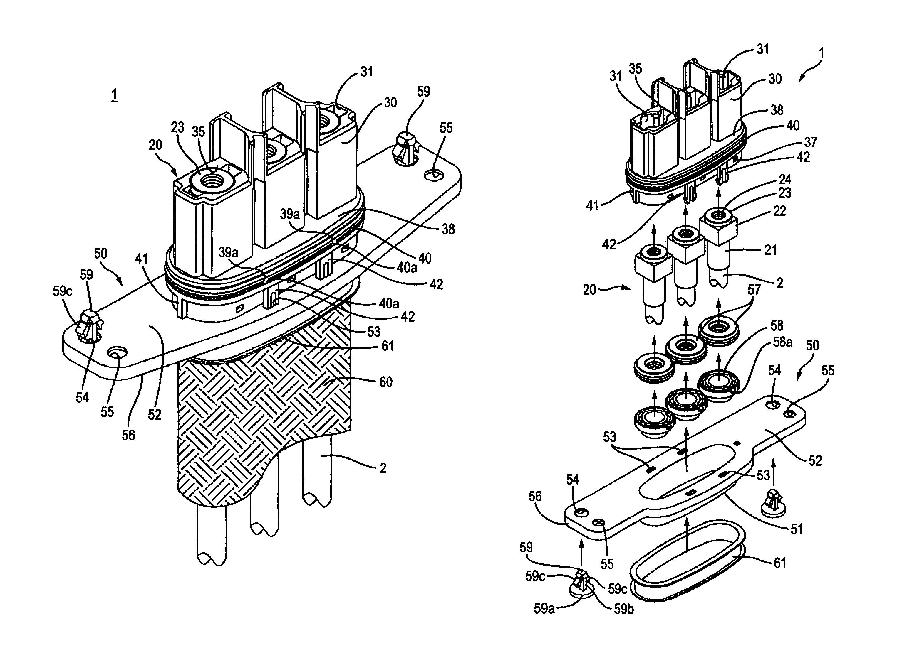
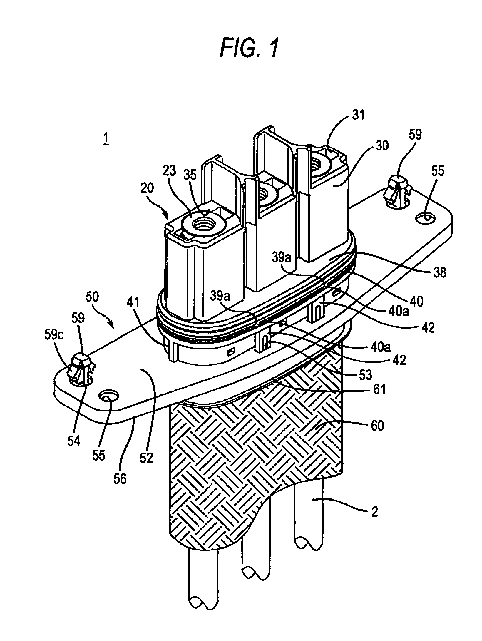
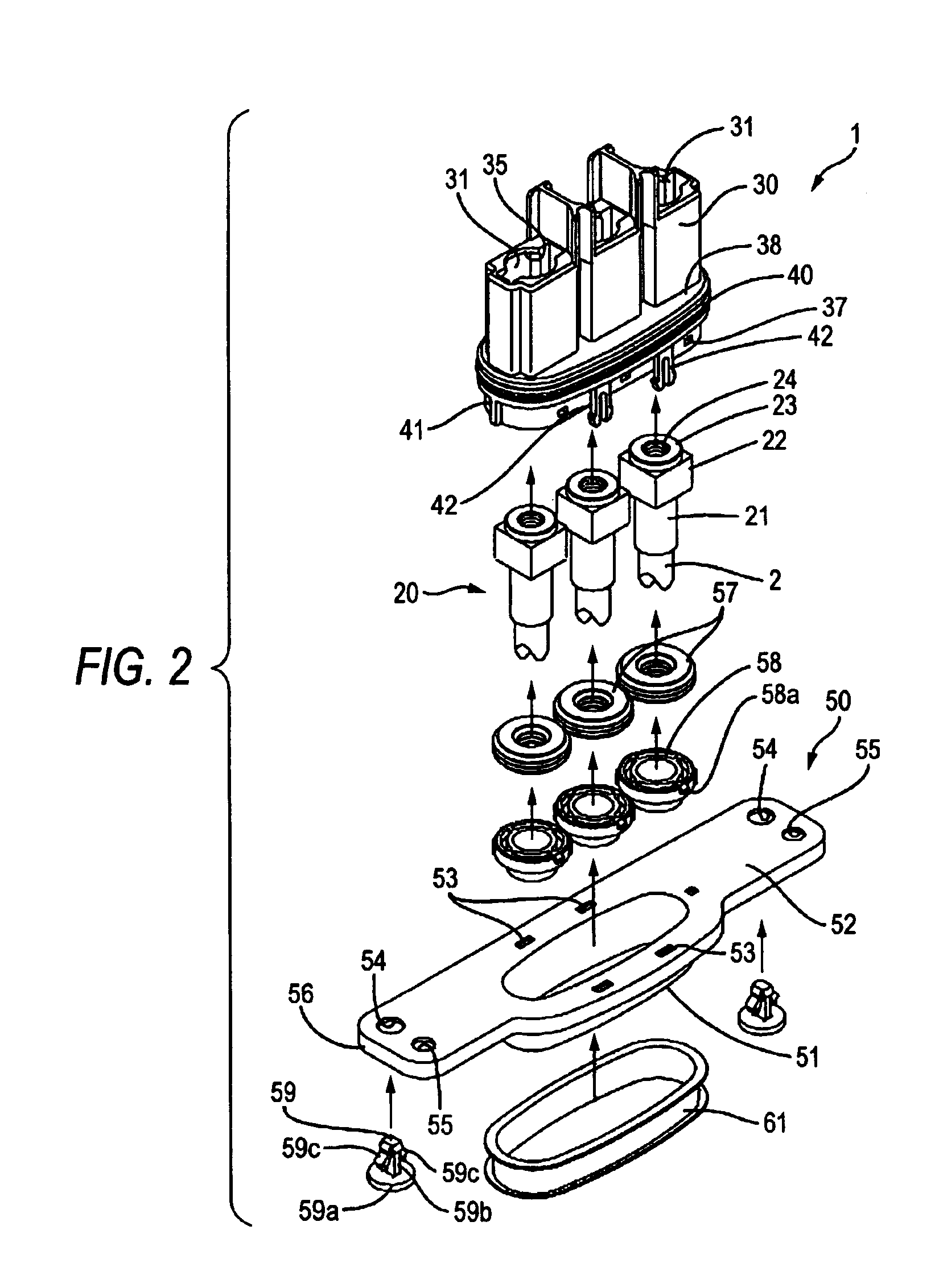
[0030]Hereinafter, a connector 1 according to the invention will be described below with reference to FIGS. 1 through 8. Incidentally, in the following description, the direction connecting the left bottom and the right top in FIGS. 1 and 2 will be defined as a horizontal (left and right) direction, and the direction connecting the left top and the right bottom in the same drawings will be defined as a front / rear direction.

[0031]The connector 1 in the first embodiment is to be connected to equipment 10 (for example, inverter unit) of an electric vehicle in upward in upward direction. The equipment 10 accommodates three equipment-side terminals 13 and an equipment main part 12 in a conductive shielding casing 11. The equipment-side terminals 13 extend from the equipment main part 12. Each equipment-side terminal 13 has a shape like a plate called a bus bar, retained in a horizontal posture and in parallel with the other equipment-side terminals 13 in the horizontal (left and right) d...

second embodiment

[0063]Hereinafter, a connector 100 according to the invention will be described with reference to FIGS. 9 through 11.

[0064]The connector 100 in the second embodiment is used for connecting a shielded wire harness 101 to equipment 110 such as an inverter unit or a motor in an electric vehicle.

[0065]The equipment 110 accommodates an equipment main part 112 and three equipment-side terminals 113 in a conductive shielding casing 111. The equipment-side terminals 113 extend from the equipment body 112. Each equipment-side terminal 113 has a shape like a plate bent into a substantially L-shape, called a bus bar. A bolt hole 114 is formed in the horizontal portion of each equipment-side terminal 113 so as to penetrate the equipment-side terminal 113 in the vertical (up and down) direction. Three circular mounting holes 115 are formed in a side wall of the shielding casing 111 so as to align in the horizontal (left and right) direction correspondingly to the equipment-side terminals 13 resp...


PUM


Abstract

A connector includes: a plurality of terminals fixedly attached to an end portion of a plurality of wires and configured to be connected to the terminals of the equipment, respectively; a housing configured to retain the plurality of terminals and to be fit into the mounting hole; and a shielding shell having conductive characteristic and fixedly attached to an end portion of a cylindrical shielding member enclosing the plurality of wires collectively, and configured to be connected to the shielding casing.

Description

BACKGROUND OF THE INVENTION[0001]1. Field of the Invention[0002]The present invention relates to a connector having shielding shell to be connected to equipment such as an inverter unit or a motor for an electric vehicle.[0003]2. Description of the Related Art[0004]A conventional connector used for connecting a plurality of shielded wires to equipment such as an inverter unit in an electric vehicle includes a shielding shell.[0005]The conventional connector used for such purpose, as disclosed in JP-A-11-026093, is structured in that wire-side terminals are fixedly attached to conductors of shielded wires and retained in a housing, while a conductive connecting member is fixedly attached to a shielding layer of each shielded wire. When the connector is to be attached to equipment, the housing is plugged into a mounting hole formed in a shielding casing of the equipment, and a bracket formed in the outer circumference of the housing is fixedly connected to the outer surface of the shi...

Claims


Application Information

Patent Timeline
IPC IPC(8): H01R11/12H01R11/11H01R9/03H01R13/648H01R13/74
CPCH01R9/032H01R11/12H01R13/648H01R13/748H01R2201/26Y10S439/939H01R13/65912
Inventor MIYAZAKI, SHO
Owner AUTONETWORKS TECH LTD
Why Eureka
Try Eureka