Intraocular lens implant having accommodative capabilities

a technology of intraocular lens and ocular lens, which is applied in the field of ophthalmologic devices, can solve the problems of loss of ability to change its shape, fading vision, and progressive hardening of the lens of every ey

Inactive Publication Date: 2005-07-26
KHOURY ELIE
View PDF8 Cites 68 Cited by
  • Summary
  • Abstract
  • Description
  • Claims
  • Application Information

AI Technical Summary

Benefits of technology

[0017]Conveniently, the shell peripheral wall defines a peripheral wall inner surface, the shell-to-lens coupling means allowing the lens to move within the shell inner volume so as to vary the relative position between the lens and the peripheral wall inner surface. Also, preferably, the shell-to-lens coupling means allows the lens to be pivotally coupled to the shell component within the shell inner volume for pivotal movement therein between lens accommodating positions.
[0044]Furthermore, even in situations wherein the capsule is unintentionally ruptured during surgery or thereafter, the proposed implant is designed so as to remain relatively functional. Still furthermore, the proposed implant is designed so as to be manufacturable using conventional forms of manufacturing and conventional materials so as to provide an implant that will be economically feasable, long lasting and relatively trouble free in operation.

Problems solved by technology

With increasing age, the lens of every eye undergoes a progressive hardening, with loss of ability to change its shape.
The cataracts may be in both eyes and, being a progressive condition may cause fading vision and eventual blindness.
The patient then wore eye glasses or contact lenses which restored vision but did not permit focusing and gave only limited depth perception.
Problems such as dislocation after implantation forced abandonment of this approach, and for some period thereafter intraocular lenses were implanted in the anterior chamber of the eye.
However, most of these designs suffer from lack of sharp variable focusing capability.
However, the prior art accommodative lenses suffer from numerous drawbacks including overall complexity leading to increased costs and decreased overall reliability.

Method used


Image

  • Intraocular lens implant having accommodative capabilities
  • Intraocular lens implant having accommodative capabilities
  • Intraocular lens implant having accommodative capabilities

Examples


Embodiment Construction

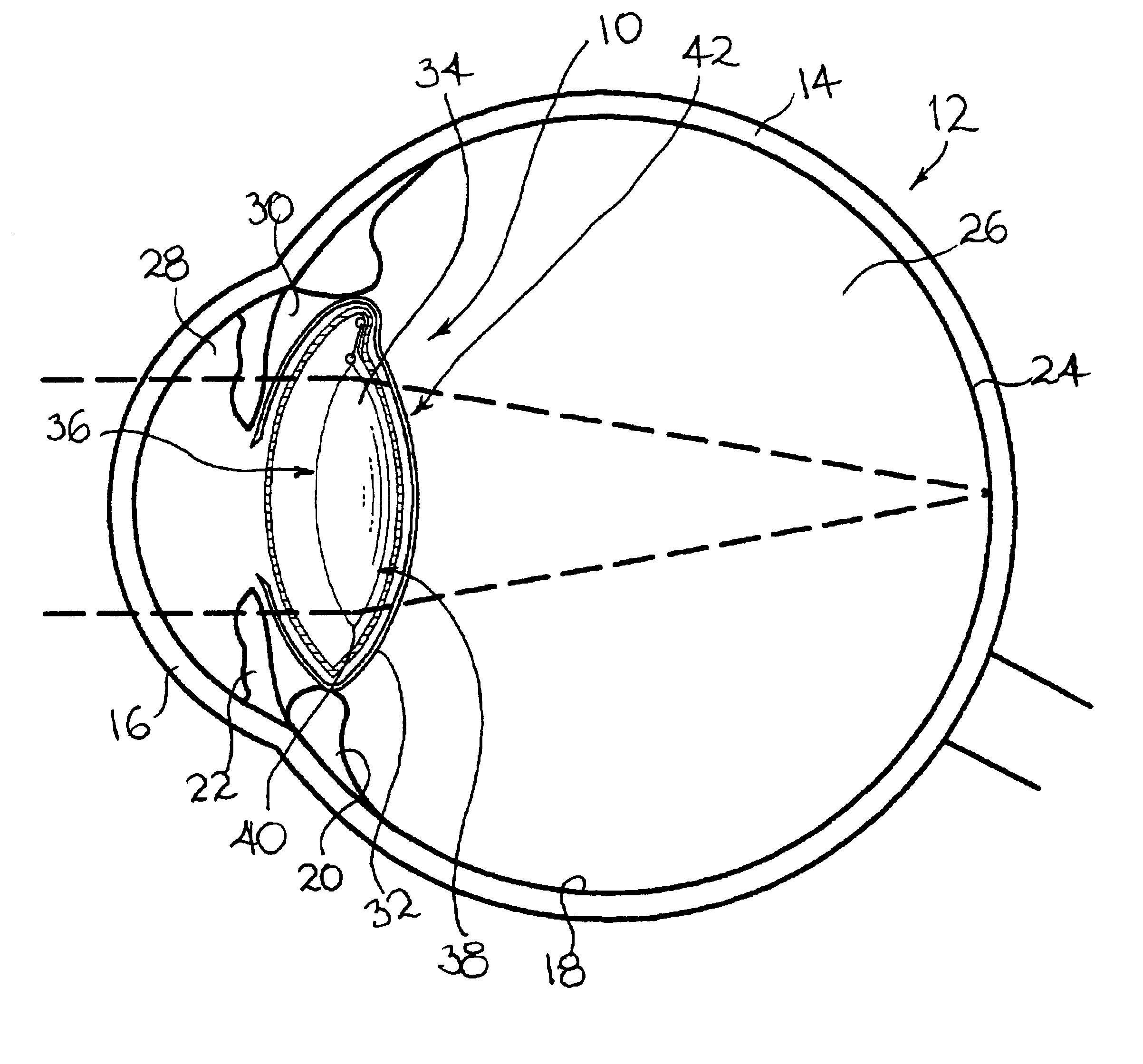
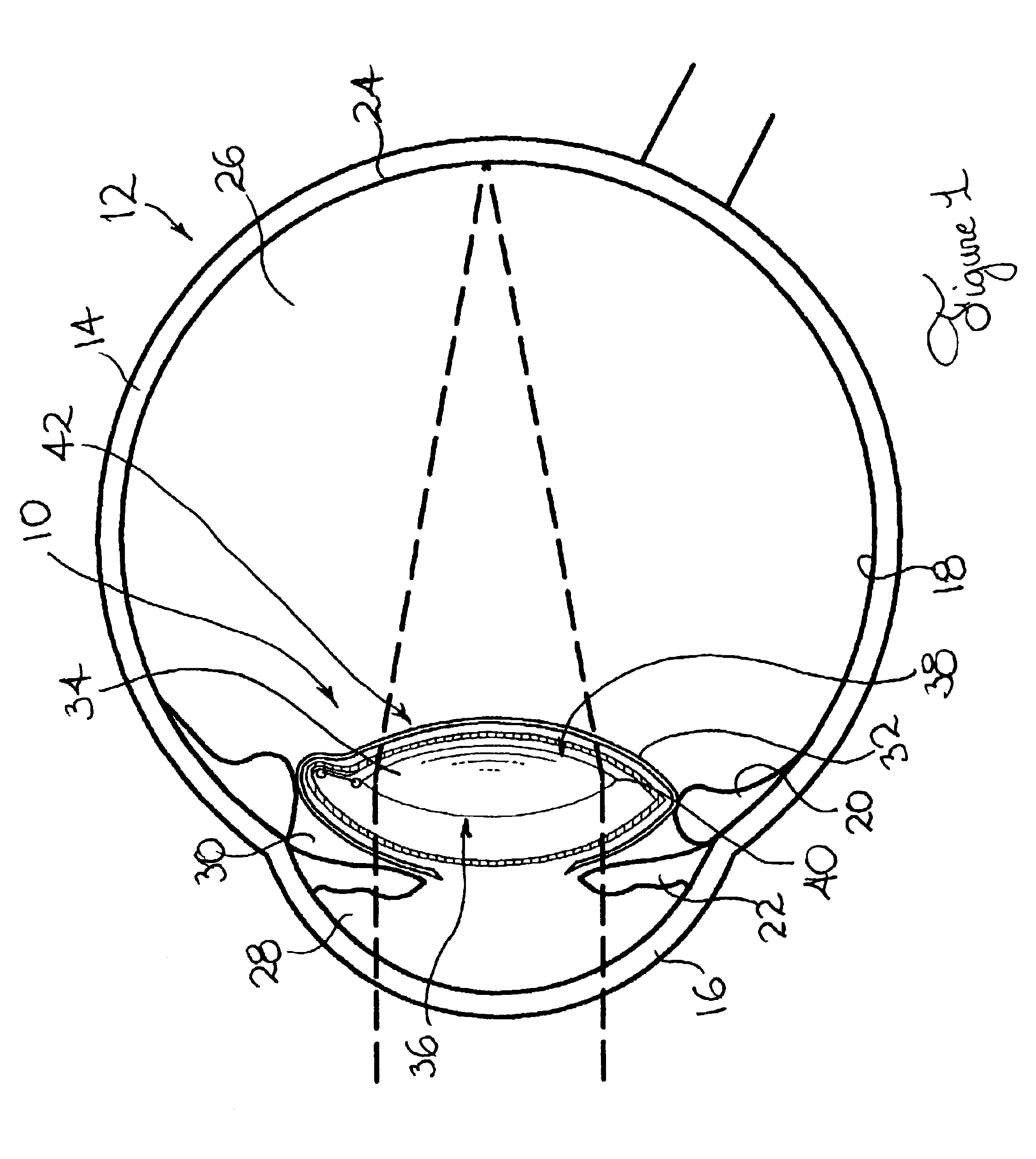
[0061]Referring to FIG. 1, there is shown an intraocular lens implant (10) in accordance with an embodiment of the present invention. The intraocular lens implant (10) is shown implanted within a schematized human eye (12).

[0062]As is well known in the art, the eye (12) has an outermost covering including a fibrous sclera (14) and a cornea (16). A pigmented vascular layer is positioned inwardly relative to the sclera (14). The pigmented vascular layer includes the choroid (18), the ciliary body (20) and the iris (22).

[0063]The eye (12) also includes a retina (24) positioned immediately under a pigmented epithelial layer. The eye (12) also includes a vitreous cavity (26) filled with a transparent gel called the vitreous humor.

[0064]The portion of the eye (12) located in front of the vitreous cavity (26) is divided into two chambers. An anterior chamber (28) extends between the cornea (16) and the iris (22). A posterior chamber (30) extends between the iris (22) and the vitreous chamb...


PUM


Abstract

An intraocular implant including a lens and a shell component. The shell component includes a shell peripheral wall encompassing a shell inner volume for protectively enclosing the lens and allowing the latter to move therein between lens accommodating positions. The lens is pivotable within the shell inner volume between a lens first position wherein the lens is in a substantially proximal relationship relative to a shell wall first segment and a lens second position wherein the lens is in a substantially proximal relationship relative to a shell wall second segment. In one embodiment of the invention, the lens peripheral edge defines a lens edge pivot portion and the shell segment joining edge defines a corresponding shell edge pivot portion, the lens and shell edge pivot portion being complementarily configured and sized so that when the lens abuttingly rests against the peripheral wall inner surface, the lens and shell edge pivot portions interact with each other for allowing the lens to pivot between the lens first and second positions.In another embodiment of the invention, the lens is pivotally suspended within the shell component for pivotal movement between the lens first and second position. In both embodiments, the lens may also pivot to a lens intermediate position in a spaced relationship relative to both the the shell wall first and second segments.

Description

FIELD OF THE INVENTION[0001]The present invention relates to the general field of ophthalmologic devices and is more particularly concerned with an intraocular lens implant having accommodative capabilities.BACKGROUND OF THE INVENTION[0002]The human eye has three concentric layers of tissue enclosing the lens and the inner media. The eyes outermost covering is the tough, fibrous sclera and its anterior transparent modification, the cornea. The cornea is the major light refractor of the eye. Below the sclera is the pigmented vascular layer of the eye, which includes the choroid, ciliary body and the iris.[0003]The vitreous cavity constitute two-thirds (⅔) of the volume of the eye. It is filled with transparent jell, the vitreous humor. The portion of the eye in front of the vitreous is divided into two compartments, the anterior chamber (between the cornea and iris) and the posterior chamber (between the iris and vitreous). The chambers are filled with aqueous humor. The innermost la...

Claims


Application Information

Patent Timeline
Patent Type & Authority Patents(United States)
IPC IPC(8): A61F2/16
CPCA61F2/1613A61F2/1627A61F2/1648
Inventor KHOURY, ELIE
Owner KHOURY ELIE
Why Eureka
Try Eureka