Electric motor control device

Active Publication Date: 2005-07-26
ROHM CO LTD
View PDF15 Cites 19 Cited by
  • Summary
  • Abstract
  • Description
  • Claims
  • Application Information

AI Technical Summary

Benefits of technology

[0012]Therefore, it is an object of the invention to detect the number of rotations and a rotating position from an induced voltage also at time of braking in the driving operation of an ele

Problems solved by technology

However, since a high-speed rotation of a disk (for example, 10,000 RPM) has recently been introduced into the market, reflecting a demand for the high-speed write/read of data into/from the disk, the applicability of the reverse rotation braking method comes to b limited for its use.
As a result, the insulation intensity of the electric motor is required to be increased or a power loss problem which leads to heat generation cannot be any more disregarded.
Consequently, the phase switching timing might be likely to be detected erroneously.
Thus, there is a possibility that the switching might be carried out in an erroneous timing.
Moreover, there is also a problem in that the rotation is carried out in a reverse direction

Method used


Image

  • Electric motor control device
  • Electric motor control device
  • Electric motor control device

Examples


Embodiment Construction

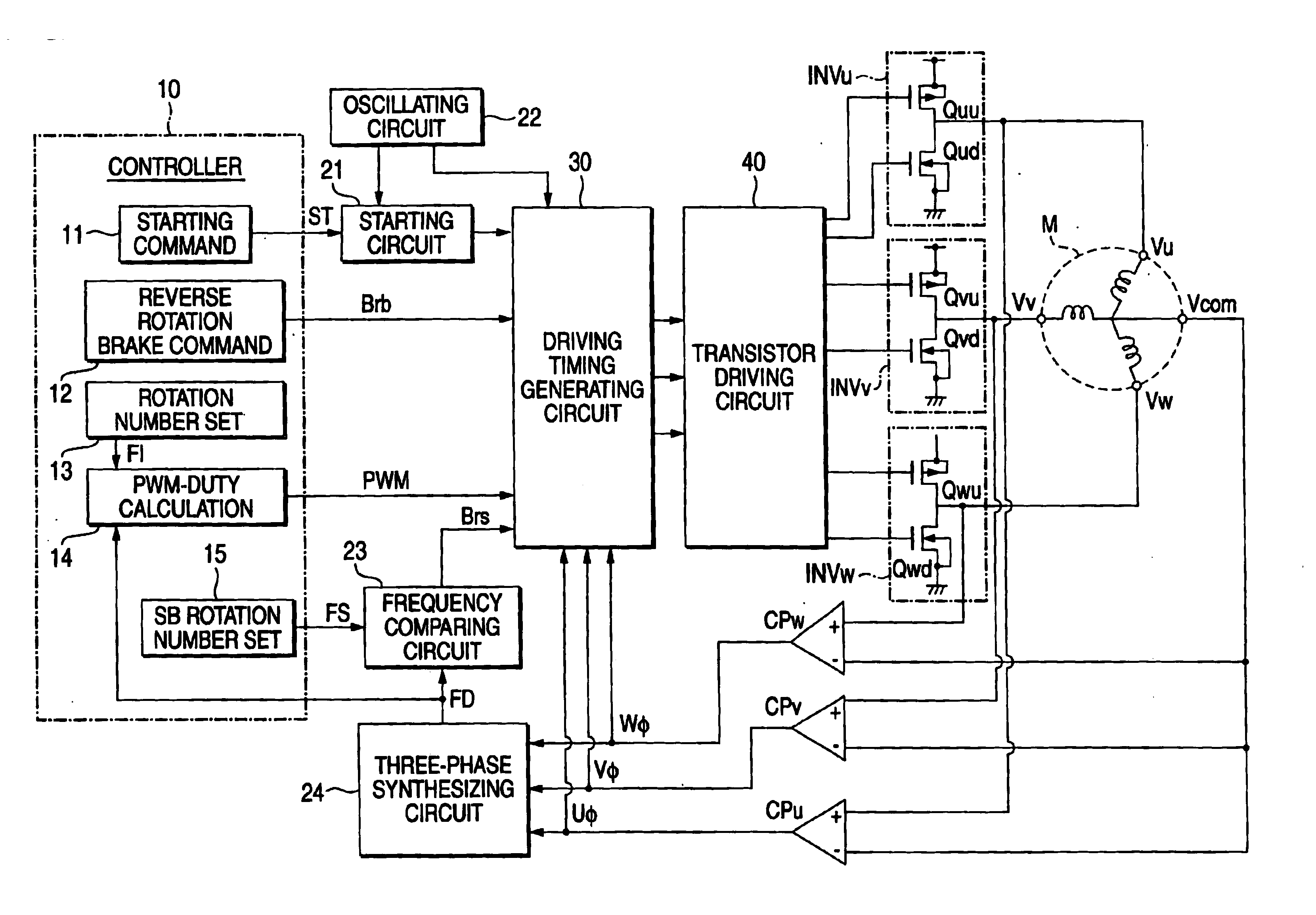
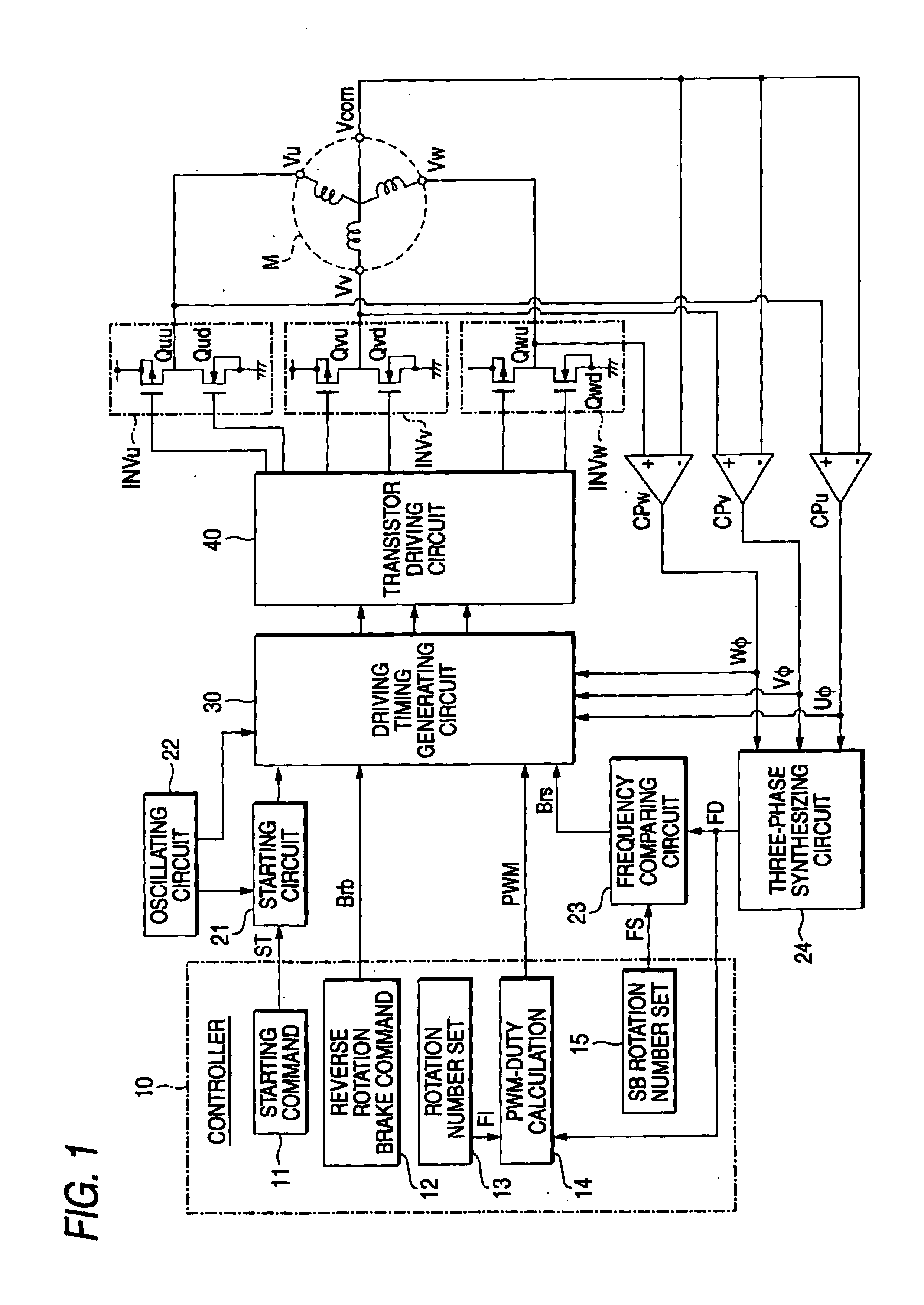
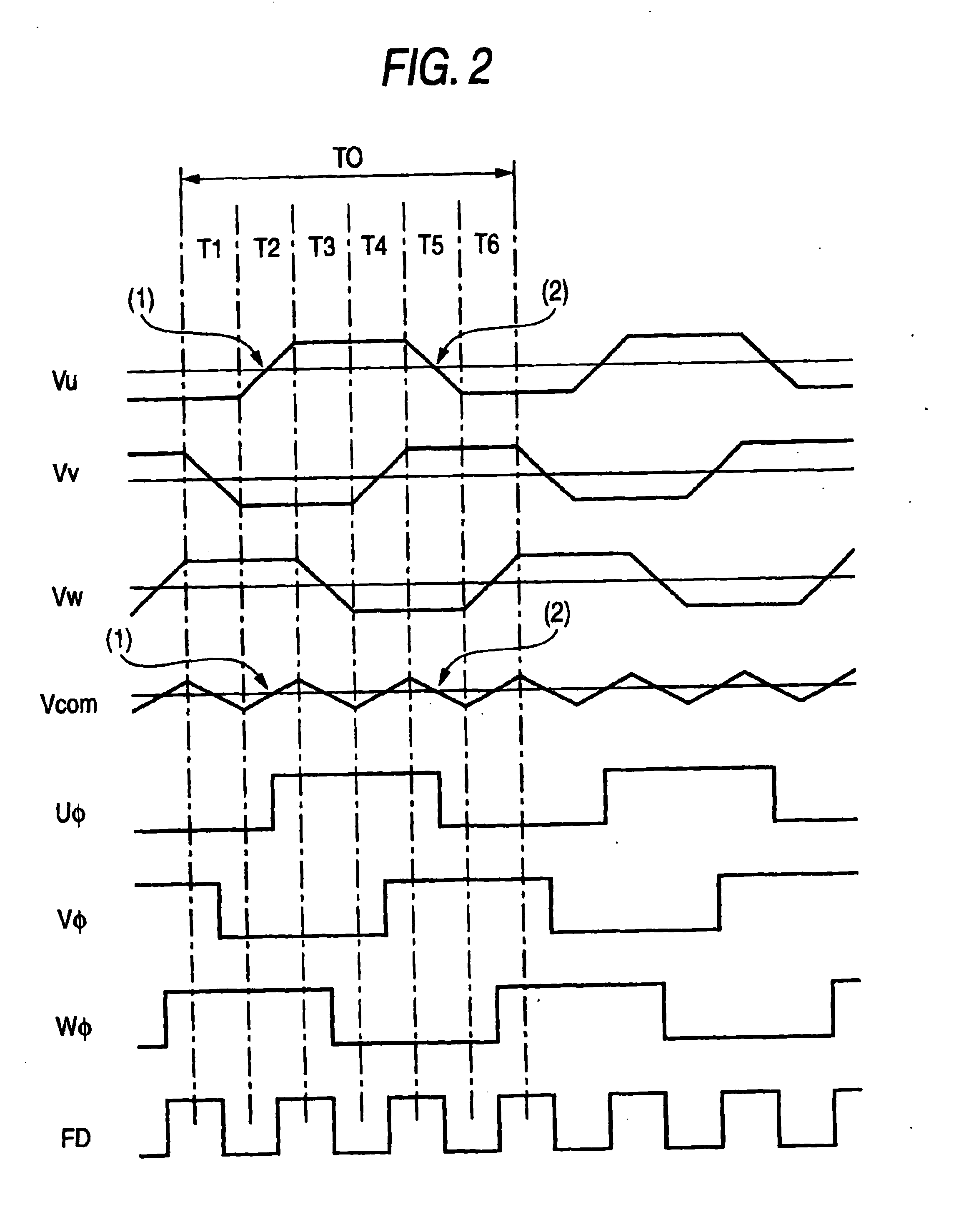
[0017]An embodiment of a control device of a sensorless motor according to the invention will be described below with reference to FIGS. 1 to 3. FIG. 1 is a diagram showing a circuit structure according to the embodiment of the invention, FIG. 2 is a timing chart showing a normal driving operation, and FIG. 3 is a timing chart showing a reverse rotation braking operation.

[0018]In FIG. 1, a three-phase sensorless motor M has driving windings having U, V and W phases which are connected to be star-shaped (Y-type), and is provided with driving winding terminals and a Y connection middle terminal which Y connects them. The driving winding terminals are connected to the output terminals of inverters INVu, INVv and INVw, respectively.

[0019]The U-phase inverter INVu has an upper transistor Quu and a lower transistor Qud connected in series between a power source and a ground, and a node is connected to a U-phase driving winding terminal. The node has a U-phase node potential Vu.

[0020]The V...


PUM


Abstract

In the driving operation of a sensorless three-phase motor to be used in a rotation at a comparatively low speed (approximately 2000 RPM or less) and to be bipolar driven, the number of rotations and a rotating position are accurately detected from an induced voltage and a reverse rotation brake is applied in an accurate phase, and furthermore, a short brake is applied at a set rotation number signal or less also in braking. Consequently, it is possible to prevent phase switching from being carried out in an erroneous timing and to prevent a rotation in a reverse direction by an inertia.

Description

BACKGROUND OF THE INVENTION[0001]1. Field of the Invention[0002]The present invention relates to a control device of an electric motor to be rotated at a comparatively low speed which is to be used in a disk device such as a CD or a DVD, and more particularly to a control device of an electric motor which accurately detects a rotating position and the number of rotations and carries out braking from a rotating state to a stop state promptly and accurately.[0003]2. Description of the Related Art[0004]Conventionally, as the methods known for stopping a three-phase motor having a driving winding for each phase being provided in a stator in a rotation state, there are so-called a short braking method where a full driving winding is short-circuited, and also known is so-called a reverse rotation braking method where a conduction state to each phase driving winding of an electric motor is made in a different state from a normal driving state such as to subject a driving winding in a condu...

Claims


Application Information

Patent Timeline
IPC IPC(8): H02P6/00H02P6/14H02P6/24H02P6/18H02P6/06H02P6/08H02P6/182
CPCH02P6/24H02P6/182H02P3/10
Inventor MAEDA, NORIHIRO
Owner ROHM CO LTD
Why Eureka
Try Eureka