Vehicle air-conditioning system

a technology for air conditioning systems and vehicles, applied in the direction of machine operation, lighting and heating apparatus, transportation and packaging, etc., can solve the problems of insufficient amount of circulating refrigerant of hot gas heater cycles, extremely small high/low differential pressure of cycles, and small amount of circulating refrigeran

Inactive Publication Date: 2005-08-02
DENSO CORP
View PDF7 Cites 17 Cited by
  • Summary
  • Abstract
  • Description
  • Claims
  • Application Information

AI Technical Summary

Benefits of technology

[0015]An object of the present invention is to provide a vehicle air-conditioning system of a dual air-conditioner type exhibiting a hot gas heater func

Problems solved by technology

Therefore, there was the problem that the refrigerant accumulated in the condenser (dormant) could not be ejected to the hot gas heater cycle side and the amount of circulating refrigerant of the hot gas heater cycle became insufficient.
However, in a vehicle air-conditioning system of the dual air-conditioner type provided with cooling evaporators at both a front seat air-conditioning unit and a rear seat air-conditioning unit, if setting the system to the cooling mode at the time of startup of heating at cold times to recover the dormant refrigerant in this way, since the cooling thermal load is small, the high/low differential pressure of the cycle becomes extr

Method used


Image

  • Vehicle air-conditioning system
  • Vehicle air-conditioning system
  • Vehicle air-conditioning system

Examples


first embodiment

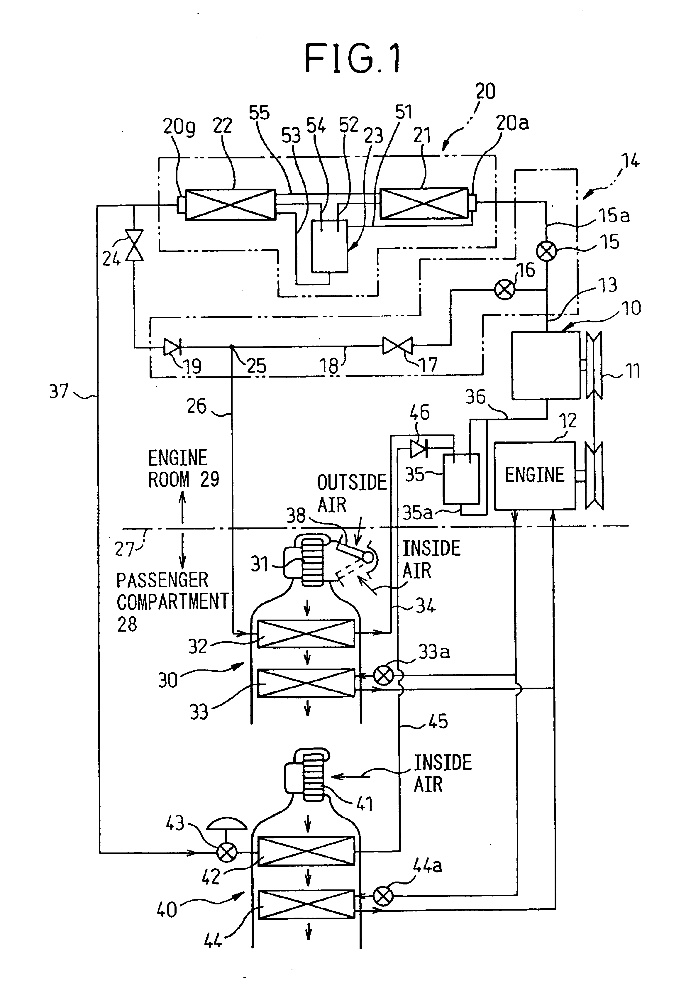
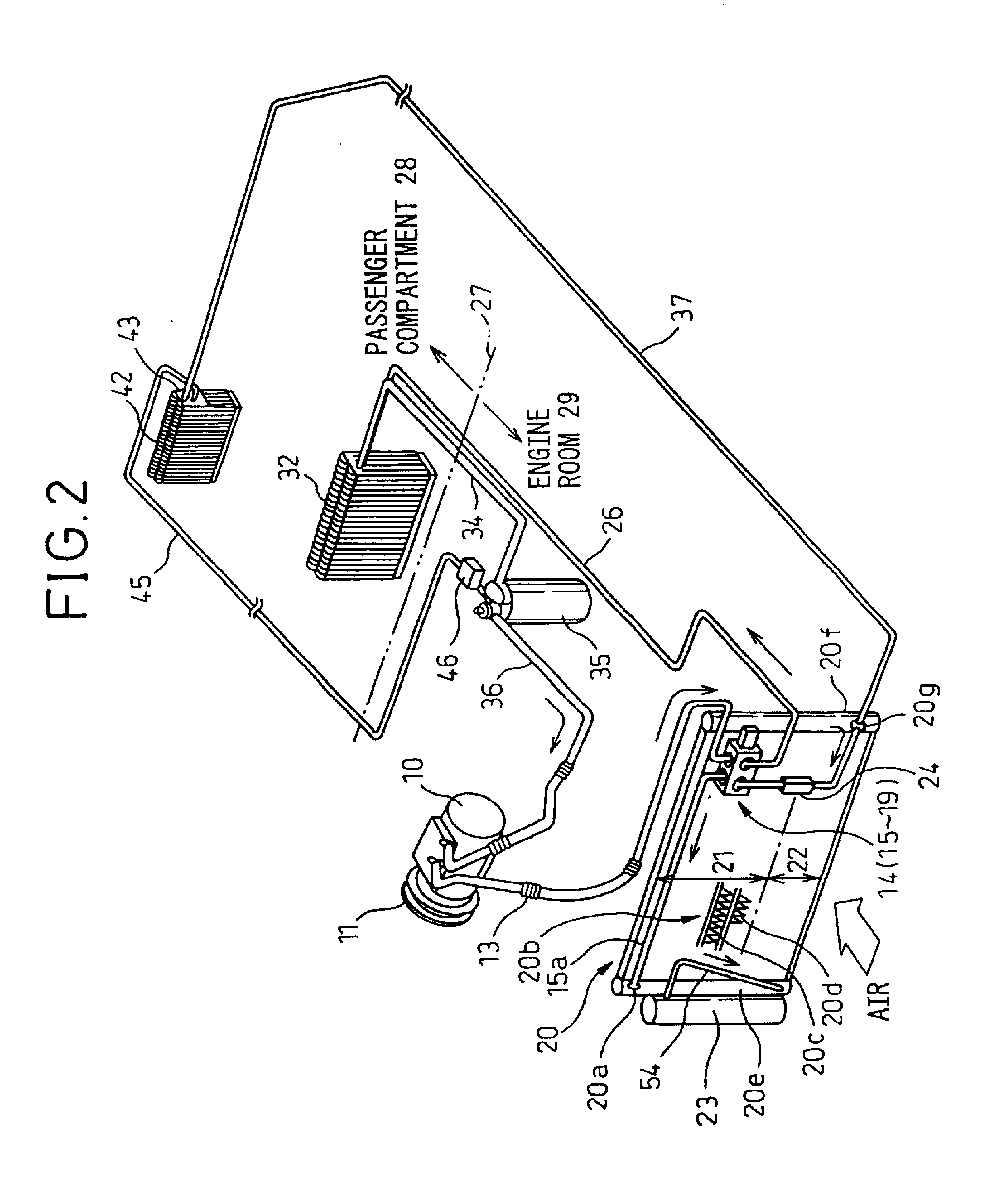
[0043]FIG. 1 illustrates the circuit configuration of the refrigeration cycle and the hot water circuit configuration of the vehicle air-conditioning system according to a first embodiment, while FIG. 2 illustrates the layout of the refrigeration cycle parts of the vehicle air-conditioning system according to the first embodiment mounted in a vehicle.

[0044]The first embodiment relates to a vehicle air-conditioning system of a dual air-conditioner system provided with both a front seat air-conditioning unit 30 for air-conditioning a front seat area of a passenger compartment 28 and a rear seat air-conditioning unit 40 for air-conditioning a rear seat area of the passenger compartment 28. The air-conditioning system is applied for example to a one-box type recreational vehicle or another vehicle having a large compartment space.

[0045]Note that the front seat air-conditioning unit 30 is mounted at the inside of an instrument panel (not shown) arranged at the front of the passenger comp...

second embodiment

[0111]In the first embodiment, at step S60 of FIG. 4, it was judged if the inside air temperature was higher than the refrigerant temperature of the rear seat evaporator 42. In the second embodiment, as shown in FIG. 6, at step S60, it is judged if at least the predetermined time t2 has elapsed after startup of the heating mode by the hot gas heater.

[0112]That is, as shown in FIG. 5, when at least the predetermined time t2 has elapsed after startup of the heating mode, the temperature of the suction air (inside air) of the rear seat evaporator 42 becomes higher than the refrigerant temperature of the rear seat evaporator 42 and the refrigerant of the rear seat evaporator 42 can absorb heat from the suction air (inside air). Therefore, as shown in FIG. 6, at step S60, it is judged if at least the predetermined time t2 has elapsed from the startup of the heating mode. If at least the predetermined time t2 has elapsed, the routine proceeds to step S70, whereby it is sufficient to opera...

third embodiment

[0113]In the first and second embodiments, the explanation was given of the example of operating the front seat blower 31 of the front seat air-conditioning unit 30 and setting the rear seat blower 41 of the rear seat air-conditioning unit 40 to the off state in the refrigerant recovery operation by the cooling mode at steps S30 of FIG. 4 and FIG. 6. In the third embodiment, as shown in FIG. 7, the refrigeration cycle is set to the state of the refrigerant recovery operation due to the cooling mode (state with cooling use solenoid valve 15 on and heating use solenoid valve 16 off) at step S30 as shown in FIG. 7, then the routine proceeds to step S35, where the front seat blower 31 is operated to blow outside air to the front seat evaporator 32. On the other hand, at the rear seat air-conditioning unit 40, the rear seat blower 41 is operated to blow inside air to the rear seat evaporator 42.

[0114]Due to this, a differential pressure of the [refrigerant pressure of rear seat evaporato...


PUM


Abstract

A vehicle air-conditioning system of a dual air-conditioner type exhibiting a hot gas heater function, which is designed to efficiently recover not only dormant refrigerant at the heater side, but also dormant refrigerant at the rear seat evaporator, which system sets the refrigeration cycle to a cooling mode and engages in a refrigerant recovery operation when starting up the heating mode by a hot gas heater cycle, then switches the refrigeration cycle to the heating mode, sets the front seat air-conditioning unit to the outside air mode at the time of the heating mode to blow outside air to the front seat evaporator by the front seat blower, then, when judging that the inside air temperature is high due to the refrigerant temperature of the rear seat evaporator at the time of the heating mode, operates the rear side blower to blow inside air to the rear seat evaporator.

Description

BACKGROUND OF THE INVENTION[0001]1. Field of the Invention[0002]The present invention relates to a vehicle air-conditioning system of a dual air-conditioner type provided with cooling evaporators at both a front seat air-conditioning unit and rear seat air-conditioning unit wherein, at the time of heating, gas refrigerant delivered from the compressor (hot gas) is directly introduced to the front seat evaporator so as to provide a hot gas heater function.[0003]2. Description of the Related Art[0004]In the past, there has been known a vehicle air-conditioning system of the dual air-conditioner type which directly introduces a gas refrigerant delivered from a compressor (hot gas) to an evaporator at the time of heating so as to provide a hot gas heater function (see Japanese Unexamined Patent Publication (Kokai) No. 2001-130245).[0005]In the related art, a hot gas bypass passage for directly connecting a compressor delivery side to an inlet side of a front seat evaporator bypassing th...

Claims


Application Information

Patent Timeline
IPC IPC(8): B60H1/00B60H1/32F25B1/00
CPCB60H1/00735B60H1/00828B60H1/00849B60H1/00914B60H2001/00942B60H1/00885B60H1/00807B60H2001/00242B60H2001/3252
Inventor KURATA, SHUNTAKANO, YOSHIAKI
Owner DENSO CORP
Why Eureka
Try Eureka