

Positive displacement flow meter method and apparatus
- Summary
- Abstract
- Description
- Claims
- Application Information
AI Technical Summary
Benefits of technology
Problems solved by technology
Method used
Image

Examples
second embodiment
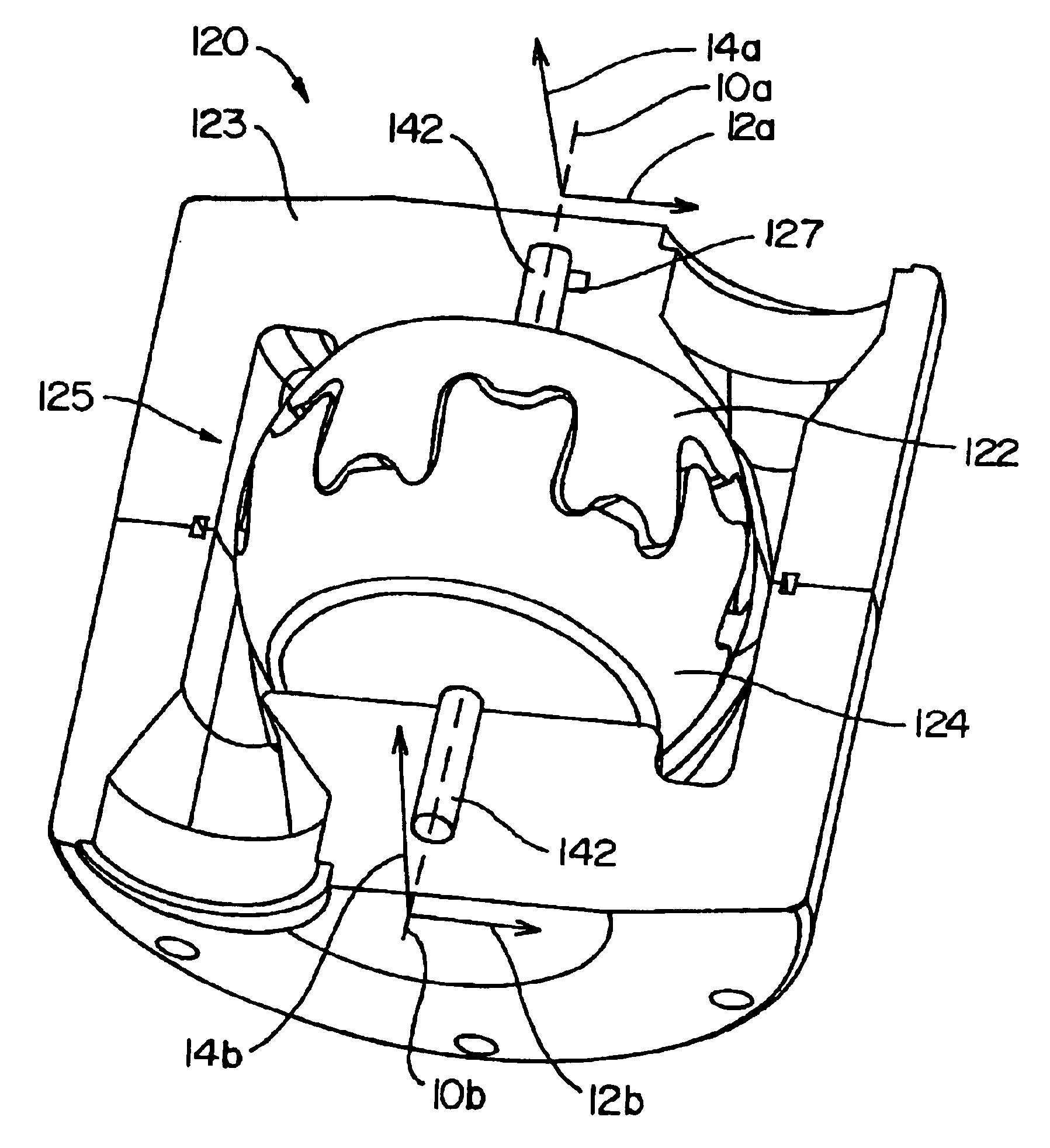
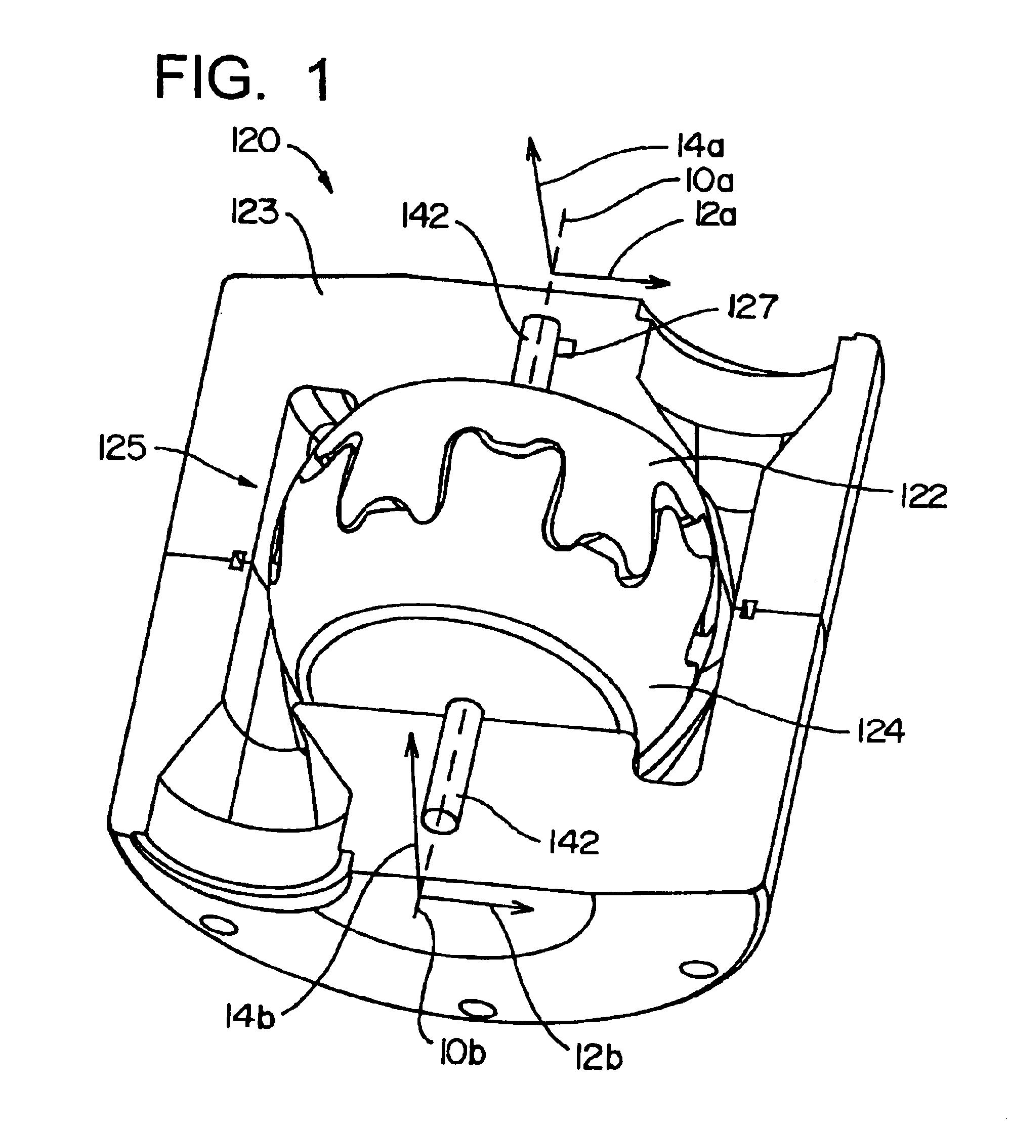
[0092]The forward portion of surface 34 defines at least part of a sphere and is adapted to engage the inner surface of the housing 22 (see FIG. 1). The spherical inner surface 40 also defines a portion of a sphere and is intimately engaged in a center bearing 23 or is a unitary piece with a center bearing 23 as shown in a second embodiment below. In the broader scope the surfaces can converge to the centerpoint of the rotors whereby removing the need of the center bearing 23.
[0093]The surfaces 36 and 38 (as well as the forward portions of surfaces 88 and 90) are described above and thoroughly in U.S. Pat. Nos. 6,036,463 and 5,755,196 which are hereby fully incorporated by reference.
[0094]The surfaces 36 and 38 comprise a concave and convex continuous surface with a precisely placed inflection point. As seen in FIG. 12, at the base portion of the lobe 32, the first surface 36 extends rearwardly to a first concave portion 52 then to a rearward portion 54 and the continuous surface co...
first embodiment
[0100]In a first embodiment, lobes 82 are symmetrical about the radially extending plane 94 (see FIG. 9) and hence the first surface 88 will be described in detail with the understanding the geometry and other relevant features relates to the second surface 90 has a substantially mirrored image about plane 94. It should be noted that certain symmetrical variations could be employed in the lobes 82 about plane 94.
[0101]The first surface 88 is shown in FIG. 14 where the rotor assembly 22 is in a bottom dead center position. The first surface 88 comprises a concave portion 96 and a convex portion 98. The inflection point line 100 is the location where the surface 88 transforms from a concave to a convex configuration. As seen in FIG. 15, the concave surface 96 has a forward portion 99 and a rearward base portion 101. The concave surface 96 further has a loss of fluid film seal line 102. The loss of engagement line 102 defines the point where the engagement surface 50 of the vane 46 rad...
PUM
 Abstract
Description
Claims
Application Information