
Automatic trim for power boats

Inactive Publication Date: 2005-08-02
FOUND FOR ADVANCEMENT OF INT SCI
View PDF1 Cites 62 Cited by
  • Summary
  • Abstract
  • Description
  • Claims
  • Application Information

AI Technical Summary

Benefits of technology

[0004]Objects of the invention include: providing low speed upward trim automatically in response to the position of the drive; trimming which is responsive to the power trim of the boat's drive; using the power trim of the boat drive to create additional trim providing lift to the stern of the boat at low speeds, and providing no drag at all at higher speeds.
[0005]According to the present invention, the stern of the boat is lifted during acceleration at very low speeds by means of at least one trim tab which is moved downwardly into a full lift position by the boat's drive when the drive is in the lowest trim position, and which is rapidly raised to a position where it is out of the water, thereby providing absolutely no drag, in response to a small amount of trim imparted to the boat's drive. By being coupled to the boat's drive, the stern-lifting trim tabs of the invention are automatically in place when desired, and out of the way when trim is not desired. The invention is readily adapted to a wide variety of inboard / outdrive and outboard boats and hulls.
[0014]The invention provides significant stern lift at lowest speeds, but provides no drag at medium and upper drive trim positions, all of the motion of the trim tab being controlled by the boat's drive in response to the power trim already installed with the boat drive.

Problems solved by technology

Static trim plates however remain in place at higher speeds and thereby produce significant drag, which reduces speed and wastes fuel.
Adjustable trim tabs are complex and require electric or hydraulic mechanisms together with operator controls and communication between the mechanisms and the controls, and require operators to adjust more than one trim control as boat speed changes.

Method used


Image

  • Automatic trim for power boats
  • Automatic trim for power boats
  • Automatic trim for power boats

Examples


Embodiment Construction

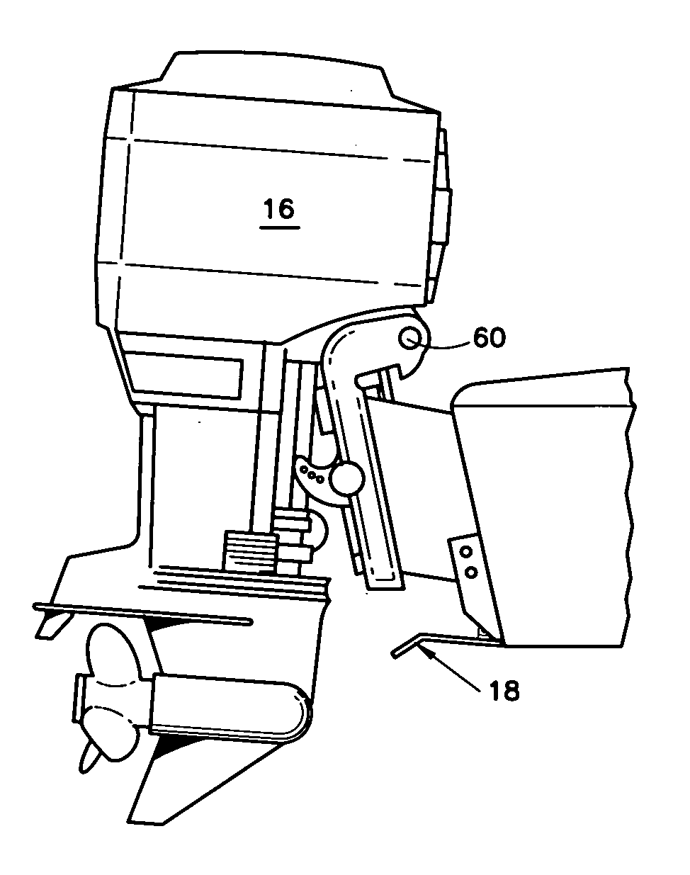
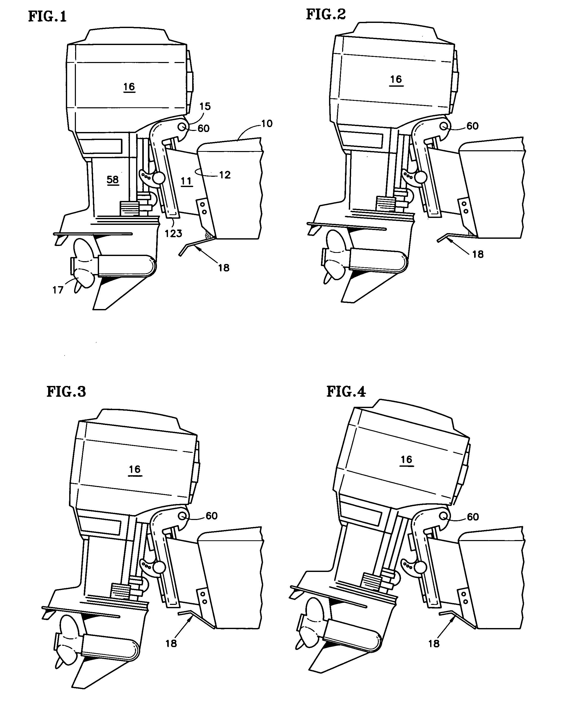
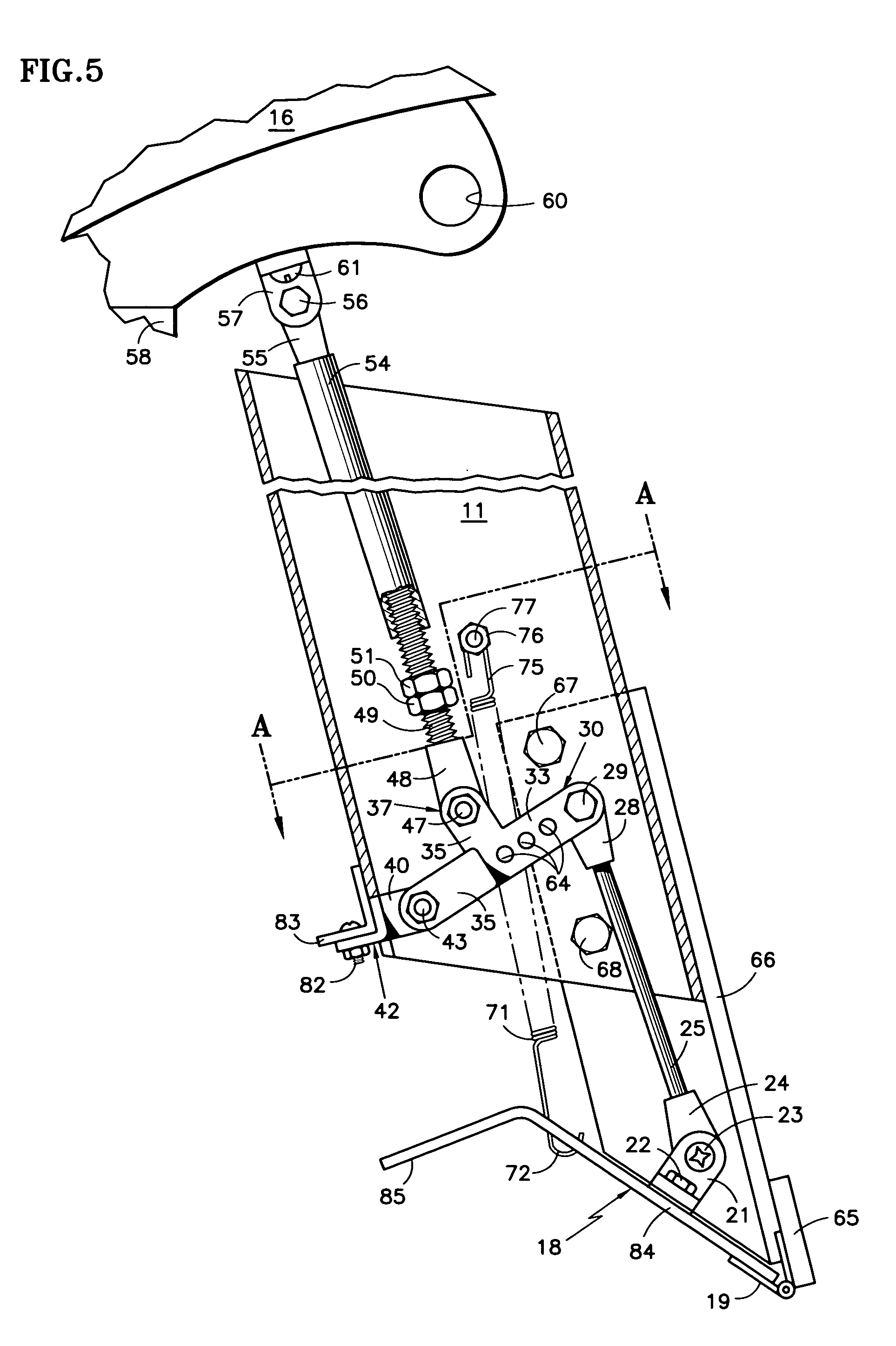
[0029]Referring to FIG. 1, a boat 10 has a jack plate 11 (or motor mount), mounted to the transom 12 of the boat. The transom bracket 15 of a propulsion system, such as an engine 16 is mounted to the jack plate 11, all in a known fashion. The engine has a propeller 17. A trim plate 18 is rotatably disposed at the base of the transom by means of a piano hinge or other suitable hinge (19, FIG. 5) so that the trim plate can rotate upwardly and downwardly in response to different trim positions of the motor 16, as illustrated in FIGS. 1–4.

[0030]In FIG. 1, the motor is in its lowermost, untrimmed position, and the trim plate 18 extends below the fair line of the hull. As the motor is trimmed a little bit, illustrated in FIG. 2, the trim plate 18 rotates upwardly to about a mid point. As the motor trim is increased, as illustrated in FIG. 3, the trim plate 18 rotates into a fully upward position, where it is out of the water and has absolutely no effect. As the trim of the motor is increa...


PUM


Abstract

A trim tab (18, 204) hinged (19) at the bottom edge of a boat transom (12, 179) is rotated into a position below the boat when the drive (58, 186) is in a lowest-most trim position, and is raised up, when the drive is above a selected pickup trim position. A push tube (58) connected to the motor (16) operates a push rod (49) and a trim tab (18). A push bar (96, 97) is moved by the drive, causing pieces (104, 105) to rotate trim tabs (18a). A fluidic slave cylinder (142) is operated by a master cylinder (134) or by a pump (148) responding to a position detector (150). Levers (164, 167) may be connected by a cable (155). A hydraulic master cylinder (195) is disposed on a part (186) of an outdrive that rotates for trim, its cylinder rod (200) contacting a fixed part (184), driving fluid to a slave cylinder (201) mounted on a fixed part (183) with its piston rod (202) moving a trim tab (204).

Description

CROSS REFERENCE TO RELATED APPLICATIONS[0001]This is a continuation-in-part of U.S. patent application Ser. No. 10 / 800,303, filed Mar. 12, 2004, now abandoned, which is in turn a continuation-in-part of U.S. patent application Ser. No. 10 / 370,965 filed on Feb. 20, 2003 now abandoned.TECHNICAL FIELD[0002]This invention relates to providing additional trim to a power boat at low speed, thereby to lift the stern and obtain plane more quickly, the trim being automatically effected by the power trim of the drive, such as the motor or outdrive.BACKGROUND ART[0003]It is well known that when a power boat accelerates from a standstill, the nose goes high and the stern goes low until a certain speed is obtained, which typically is between 20 and 30 miles per hour. Then the boat levels off and is said to be on plane. It is for this reason that transoms tilt so as to be closer to the bow below the water line, thereby to provide some upward thrust on the stern during initial acceleration. Modern...

Claims


Application Information

Patent Timeline
IPC IPC(8): B63B1/22B63B1/16B63H20/08
CPCB63H20/08B63H20/10B63B39/061
Inventor D'ALESSANDRO, DAVID A.
Owner FOUND FOR ADVANCEMENT OF INT SCI
Learn More