
Multifunctional airtight floor drain apparatus

A multi-functional, floor drain technology, applied in water supply installations, indoor sanitary plumbing installations, buildings, etc., can solve the problems of floor drain deodorization, poor insect protection, and easy evaporation of floor drain water seals, and achieves simple installation, large drainage, and good self-contained water. The effect of cleansing ability

Inactive Publication Date: 2008-12-24
田樽吉
View PDF0 Cites 13 Cited by
  • Summary
  • Abstract
  • Description
  • Claims
  • Application Information

AI Technical Summary

Problems solved by technology

[0003] The purpose of the present invention is to solve the problem that the current floor drain still has deodorization and insect prevention, is easy to be blocked by hair, cotton fabric and other dirt, and the water seal of the floor drain is easy to evaporate. A multifunctional airtight floor drain device proposed

Method used


Image

  • Multifunctional airtight floor drain apparatus
  • Multifunctional airtight floor drain apparatus
  • Multifunctional airtight floor drain apparatus

Examples


Embodiment 1

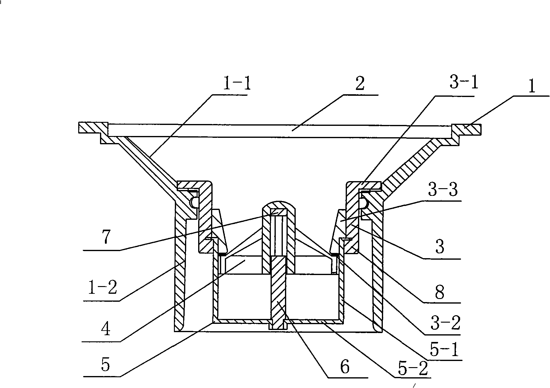
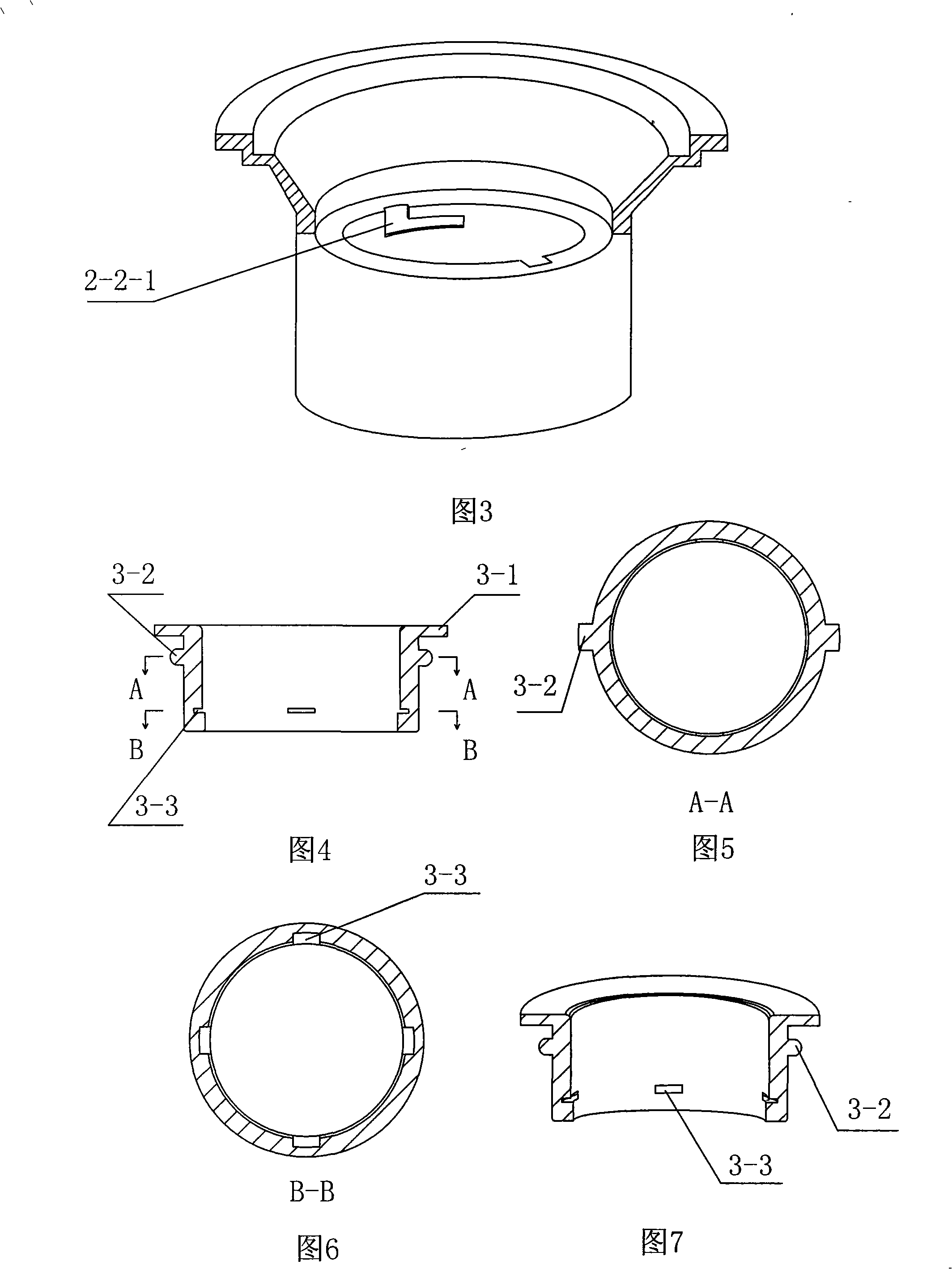
[0035] see figure 1 , Figure 3 to Figure 13 , a multifunctional airtight floor drain device, including: floor drain housing 1, grid floor drain cover 2; one end of the floor drain housing is a bowl-shaped water inlet 1-1 with a large top and a small bottom, and the other end is a straight tube 1-2, and the grid floor drain cover At the large mouth of the upper end of the bowl-shaped water connection, the straight cylinder is connected with the small mouth of the water connection; a sealed water discharge device is installed in the floor drain housing, and the airtight water discharge device includes: a cylindrical closed bracket 3, a floating cover 4, and a floating cover bracket 5 and the elastic support body; the cylindrical closed bracket penetrates into the straight cylinder of the floor drain housing, the upper end 3-1 of the cylindrical closed bracket is closed and connected with the straight cylinder of the floor drain housing at the bowl-shaped water receiving mouth e...

Embodiment 2

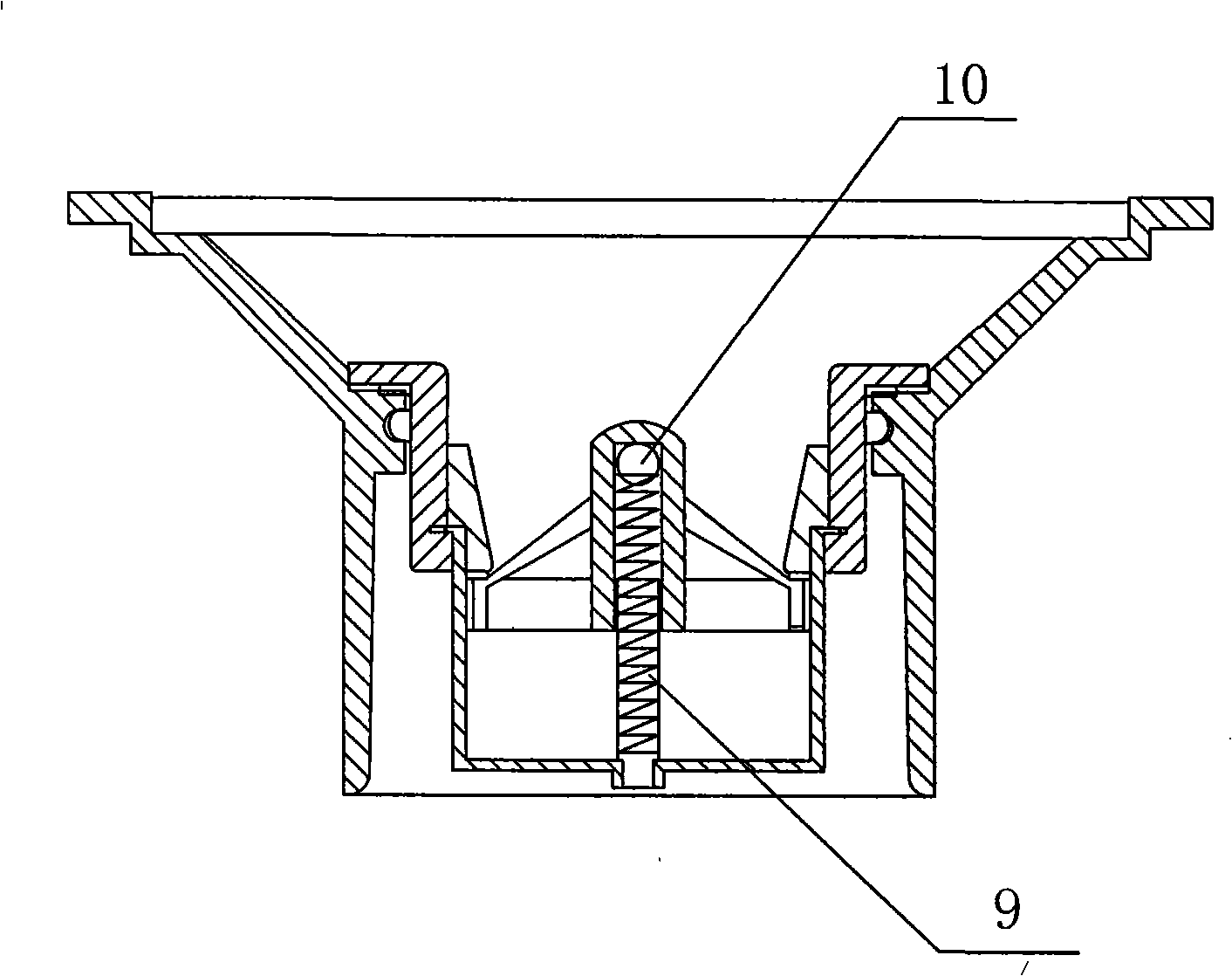
[0043] see figure 2 And embodiment 1, the difference between this embodiment and embodiment 1 is that described elastic support body is spring 9 and ball head body 10 (this embodiment is ball), and one end of spring is fixed on the center of floating cover support tray, and ball head body Installed on the other end of the spring, the floating cover is sleeved on the spring. Due to the effect of the spring, the floating cover floats up, and the periphery of the upper end of the floating cover pushes against the lower end surface of the cylindrical closed bracket.

Embodiment 3

[0045] see Figure 14 with Figure 15 , When the floor drain device is applied to the side wall drainage appliance, the grid floor drain cover and the floor drain shell are closed at 90 degrees.


PUM


Abstract

The invention relates to a multifunctional sealed floor drain device, comprising a floor drain housing and a grid floor drain cover, wherein, the floor drain housing comprises a bowl-shaped water connector with big upper part and small lower part and a straight cylinder which is arranged on a small opening end of the water connector; a sealed water drainage device is arranged inside the floor drain housing and comprises a cylindrical sealed bracket, a float cap, a float cap bracket and an elastic supporting body; the upper end of the cylindrical sealed bracket is in sealing connection with the straight cylinder of the floor drain housing at the small opening end of the bowl-shaped water connector of the floor drain housing; the float cap bracket is supported with a tray on one hanging arm, the elastic supporting body with the float cap is arranged in the center of the tray of the float cap bracket, a sleeve is arranged in the center of the float cap and is sleeved on the elastic supporting body on the float cap bracket, and the periphery at the upper end of the float cap is pressed against the lower end surface of the cylindrical sealed bracket. The multifunctional sealed floor drain device has the advantages over the prior art that: the odor removing and separating effect is good, the water discharge amount is superlarge, the phenomenon of winding does not exist, and the self-cleaning ability and the sealing ability are good and are not weakened due to the elongated use time.

Description

technical field [0001] The invention relates to building components for decoration, in particular to a multifunctional airtight floor drain device, which is applied to floor drains connected to sewer pipes in toilets, laundry rooms, kitchens, etc. of various buildings. Background technique [0002] All kinds of floor drain devices currently on the market are based on the reverse water principle; when the water stored in the floor drain dries up when not in use for a long time, this kind of floor drain will lose its anti-odor effect; these anti-odor floor drains can only be solved temporarily The problem is that if it is used for a long time, the aftertaste phenomenon still occurs. At the same time, this kind of floor drain cannot prevent the occurrence of the backflow problem. Another kind of anti-backflow floor drain has an anti-backflow hydrophobic cover through the connecting rod in the middle, but once the connecting rod is blocked by hair, cotton fabrics and other dirt,...

Claims


Application Information

Patent Timeline
Patent Type & Authority Applications(China)
IPC IPC(8): E03C1/282
Inventor 田樽吉
Owner 田樽吉
Learn More