
Vapor recovery system with ORVR compensation

a recovery system and orvr technology, applied in liquid transferring devices, liquid handling, packaging goods types, etc., can solve the problems of wasting energy, ingesting excessive air into the underground storage tank, and increasing wear and tear of the vacuum pump

Inactive Publication Date: 2005-08-02
VEEDER ROOT
View PDF38 Cites 25 Cited by
  • Summary
  • Abstract
  • Description
  • Claims
  • Application Information

AI Technical Summary

Benefits of technology

The present invention introduces a check valve into a boot in place of the always open air flow apertures. The check valve closes in the presence of positive pressure and opens in the presence of negative pressure. The check valve can be used in both balance systems and vacuum assist systems. It can be positioned in different locations in the vapor return line and can be used with a pressure sensor to infer the presence or absence of an ORVR vehicle and adjust the vapor recovery system accordingly. The check valve and pressure sensor can be used with a constant speed pump, a proportional valve, or a variable speed pump. The vapor recovery system can be throttled back or turned off by adjusting the speed of the pump or the proportional valve.

Problems solved by technology

A problem arises when an ORVR vehicle is fueled at a fuel dispenser having a vacuum assist vapor recovery system.
This competition wastes energy, increases wear and tear on the vacuum pump, and may ingest excessive air into the underground storage tank.
Another problem has been discovered when ORVR vehicles are fueled at balance-type vapor recovery fuel dispensers where a seal is formed between the nozzle and the vehicle fuel tank.
Specifically, the ORVR system of the vehicle may create a negative pressure that draws vapors from the underground storage tank into the fuel tank of the vehicle and may reduce pressure levels in the underground storage tank.
This increase in the negative pressure may cause a nuisance shut-off where the nozzle valve prematurely closes, stopping the delivery of fuel.
However, when the vehicle being fueled is not an ORVR vehicle, the apertures allow vapor-laden air to escape into the atmosphere, defeating the purpose of the vapor recovery systems.

Method used


Image

  • Vapor recovery system with ORVR compensation
  • Vapor recovery system with ORVR compensation
  • Vapor recovery system with ORVR compensation

Examples


Embodiment Construction

[0031]The embodiments set forth below represent the necessary information to enable those skilled in the art to practice the invention and illustrate the best mode of practicing the invention. Upon reading the following description in light of the accompanying drawing figures, those skilled in the art will understand the concepts of the invention and will recognize applications of these concepts not particularly addressed herein. It should be understood that these concepts and applications fall within the scope of the disclosure and the accompanying claims.

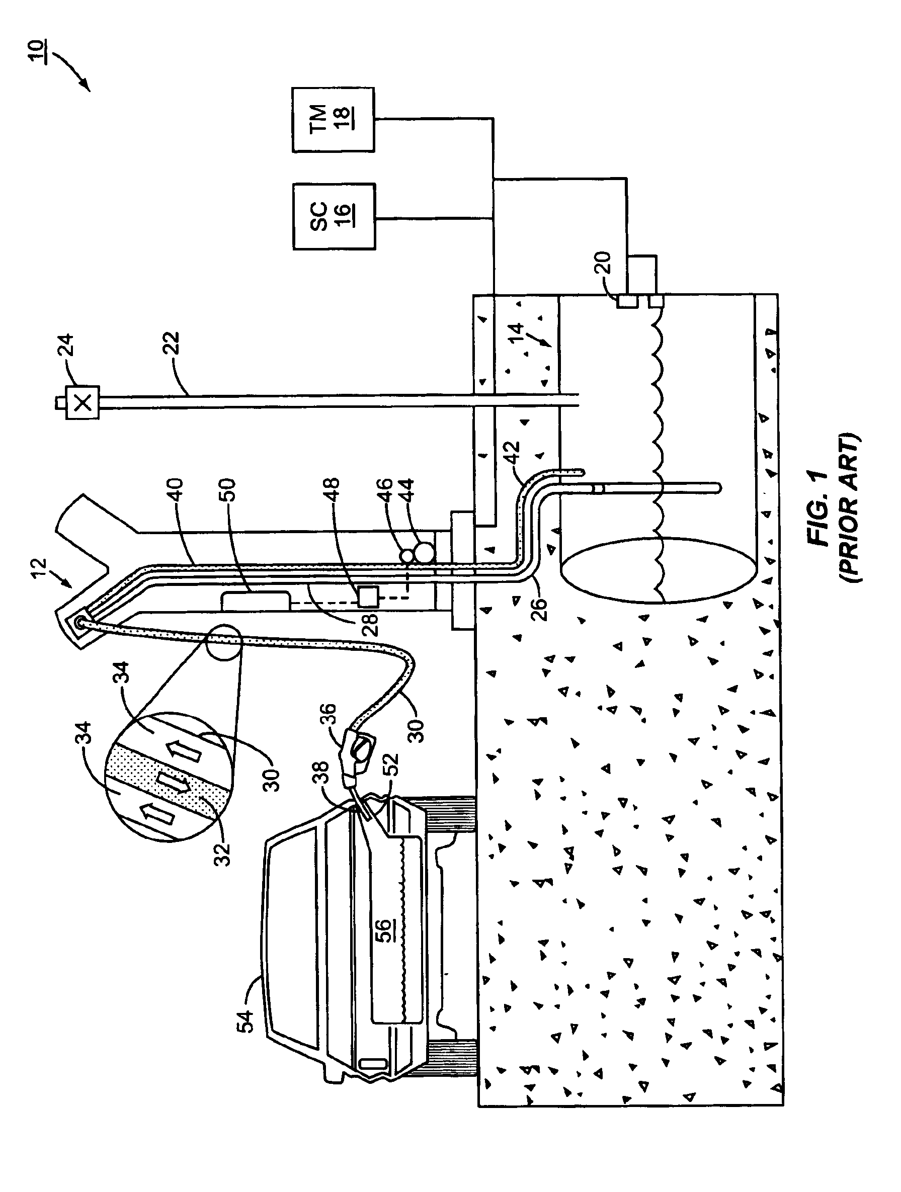
[0032]Referring now to the drawings in general and FIG. 1 in particular, a conventional fueling environment 10 is illustrated. The fueling environment 10 includes a plurality of fuel dispensers 12 (only one shown for conciseness) fluidly coupled to an underground storage tank 14 and electrically connected to a site controller (SC) 16 and / or a tank monitor (TM) 18. The fuel dispenser 12 may be an ENCORE® or ECLIPSE® fuel dispenser ...


PUM

PropertyMeasurementUnit
pressureaaaaaaaaaa
constant speedaaaaaaaaaa
speedaaaaaaaaaa

Abstract

A fuel dispenser with a booted nozzle for vapor recovery is modified to include check valves in a vapor return path. The check valves selectively allow atmospheric air into the vapor return path to alleviate nuisance shut offs at the nozzle when ORVR vehicle is being fueled. The check valves may be included anywhere in the vapor return path between the nozzle and the vapor recovery vacuum assist pump. The fuel dispenser may further include a pressure sensor in the vapor return line so that the fuel dispenser can determine if the vehicle is an ORVR vehicle or not. If the fuel dispenser determines that an ORVR vehicle is present, the fuel dispenser may modify the operation of the vapor recovery system.

Description

FIELD OF THE INVENTION[0001]The present invention relates to a vapor recovery system in a fuel dispensing environment that compensates for the presence of an onboard refueling vapor recovery (ORVR) vehicle.BACKGROUND OF THE INVENTION[0002]Automobiles are an indispensable part of everyday life to many people. Coupled with the existence of automobiles is a requirement for an energy source to provide the motive force to the wheels of the automobiles. The vast majority of the vehicles currently on the road require gasoline or diesel fuel as this energy source. As a result, vehicles are equipped with fuel tanks that must be filled periodically as the fuel is depleted. During a conventional or standard fueling operation, incoming fuel displaces fuel vapor from the head space of the fuel tank. The displaced fuel vapor exits through the filler pipe of the vehicle into the atmosphere.[0003]The Environmental Protection Agency and various state agencies including the California Air Resources B...

Claims


Application Information

Patent Timeline
Patent Type & Authority Patents(United States)
IPC IPC(8): B67D5/01B67D5/378B67D5/04B67D5/37B67D7/04B67D7/54
CPCB67D7/0478B67D7/54
Inventor RIFFLE, ERIC
Owner VEEDER ROOT
Learn More