Shock, vibration and acoustic isolation system

a technology of shock isolation and vibration, applied in the field of shock isolation systems, can solve the problems of significant cost, military equipment, and significant delay in the deployment of state-of-the-art technologies

Inactive Publication Date: 2005-08-02
HUNTINGTON INGALLS
View PDF29 Cites 47 Cited by
  • Summary
  • Abstract
  • Description
  • Claims
  • Application Information

AI Technical Summary

Problems solved by technology

Unfortunately, such militarized equipment has two significant drawbacks.
First, specially designing each piece of equipment to withstand challenging operational environments can impose significant costs.
Second, because each piece of equipment must be specially designed to meet testing criteria, the deployment of state-of-the-art technologies can be significantly delayed.
For instance, an improved flat screen display technology may be readily available for commercial applications, but it may be years before the technology can be incorporated into military equipment.
One challenge presented by COTS equipment, however, relates to its ability to pass shock and vibration requirements.
However, COTS equipment tends to have limited capabilities to withstand shock and vibration motions, and, therefore, tends to be unsuitable for being rigidly mounted to shipboard structures.
The design of the shock absorption mounts used to protect COTS equipment runs into the inherent difficulty of designing into a single isolator the ability to perform equally well as a shock isolator and a vibration isolator.
This problem arises due to the fact that a good vibration isolator tends to be a poor shock isolator and a good vibration isolator tends to be a poor shock isolator.
Most attempts to solve the combined isolation problem with a passive device have met with limited success, particularly in shipboard isolation applications where many inputs are often present simultaneously.
This inevitably leads to modifying vibration isolators to survive shock inputs and / or modifying shock isolators to perform adequately as vibration isolators.
Other environments present similar design difficulties.
Another problem presented to the designer is that the damping mechanism used in a shock isolation system must provide a force that is matched to the mass of the equipment being isolated.
Given the frequency of equipment change-out and upgrades, this is a significant drawback.

Method used


Image

  • Shock, vibration and acoustic isolation system
  • Shock, vibration and acoustic isolation system
  • Shock, vibration and acoustic isolation system

Examples


Embodiment Construction

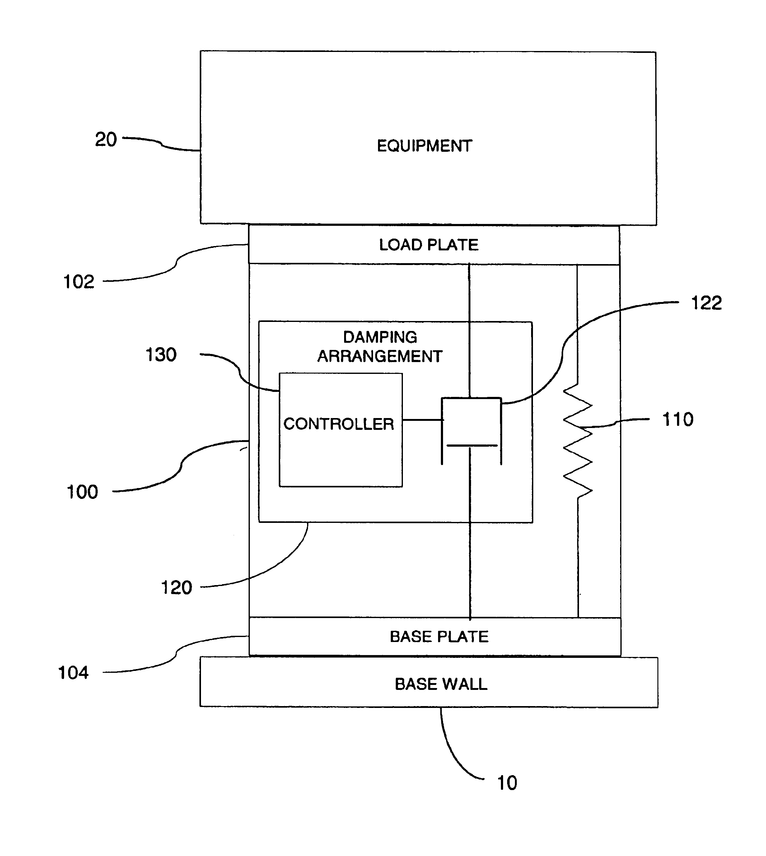
[0028]Shipboard systems are subject to multiple vibratory and shock inputs. In such environments, semi-active isolation systems may be more successful than a passive system. A semi-active isolation system can be designed to simultaneously isolate equipment from many combined and varying inputs. The present invention contemplates the combination of a semi-active damper with a passive spring element to provide an isolation system that performs well as both a vibration isolator and a shock isolator.

[0029]Combining shock and vibration isolation into a single package is highly beneficial in that the single combined isolation system replaces two separate systems. This can significantly reduce weight and increase available volume, which is particularly important in submarine applications where space is limited. Also, with varying and diverse inputs, a combined semi-active / passive isolation system can be designed to perform better than separate passive shock and vibration isolation systems ...


PUM


Abstract

A shock and vibration isolation system for mounting equipment to a base wall uses a semi-active damper in parallel with a spring arrangement to provide optimum isolation with respect to both shock and vibration. The system comprises a load plate configured for attachment of the equipment thereto and a base plate configured for attachment to the base wall. The base plate is substantially parallel to the load plate with a spring arrangement disposed intermediate the load plate and the base plate. The spring arrangement engages the load plate and the base plate to bias the load plate and the base plate in a separated relationship. The system also comprises a damping arrangement disposed intermediate the load plate and the base plate. The damping arrangement is adapted for providing a selectively variable reaction force to the load plate and the base plate responsive to a relative displacement of the load plate with respect to the base plate.

Description

RELATED APPLICATIONS[0001]This application is a continuation of application Ser. No. 09 / 963,566, filed Sep. 27, 2001 now U.S. Pat. No. 6,752,250 this application is also related to U.S. application Ser. No. 10 / 662,731, filed Sep. 15, 2003.FIELD OF THE INVENTION[0002]The present invention relates generally to isolation systems used to support and protect sensitive equipment installed on an aircraft, ship, or submarine and more particularly to an isolation system that protects such equipment against shock and vibration and also minimizes the transmission of acoustic energy from the isolated equipment to the supporting structure.BACKGROUND OF THE INVENTION[0003]Traditionally, the U.S. Government and other governments have required that electronic equipment and other sensitive equipment used aboard military vessels, such as aircraft, ships, and submarines, be specifically designed and manufactured so as to withstand these vessels' challenging operational environments. Accordingly, suppl...

Claims


Application Information

Patent Timeline
Patent Type & Authority Patents(United States)
IPC IPC(8): B60G17/08B60G17/06B60G13/14B60G13/00F16F15/02F16F9/05
CPCB60G13/14B60G17/08F16F9/05F16F15/022B60G2202/314F16F2224/043F16F2224/045F16F2230/18
Inventor TANNER, EDWARD T.
Owner HUNTINGTON INGALLS
Why Eureka
Try Eureka