Clutch driven disk with predamper

a technology of clutches and predampers, which is applied in the direction of mechanical actuated clutches, friction linings, couplings, etc., can solve the problems of limited compression of damping springs, unsatisfactory operating conditions, and limited relative rotation between them, so as to reduce the axial width of the driven disk

Inactive Publication Date: 2005-08-02
EATON INTELLIGENT POWER LTD
View PDF8 Cites 6 Cited by
  • Summary
  • Abstract
  • Description
  • Claims
  • Application Information

AI Technical Summary

Benefits of technology

[0008]A driven disk is disclosed that includes a rotatable disk assembly including a disk plate. The driven disk also includes a hub assembly having an inner hub and an outer hub rotatable relative to the inner hub and secured to at least one cover plate. The hub assembly is rotatable relative to the disk assembly. The driven disk also includes a predamper having a driving element and a driven element. The driving element includes the cover plate and the driven element includes a predamper driven plate fixed to the inner hub. The cover plate includes a number of apertures and the predamper driven plate includes a number of sockets at least partially aligned with the apertures in the cover plate. An energy storage member is disposed within the sockets in the cover plate and the predamper driven plate. The energy storage member absorbs torque as a function of relative rotation between the inner hub and the outer hub. Among other things, the predamper of the present invention reduces the axial width of the driven disk, particularly when compared to the prior art, and allows the optional incorporation of a hysteresis component into the predamper if desired.

Problems solved by technology

When the engine is drivingly connected with the transmission by the clutch, vibrations are transmitted through the clutch and into the transmission and other drive-train components, producing undesirable operating conditions, such as gear rattle.
Compression of the damping springs is limited by stops disposed between the hub and the clutch disk, limiting relative rotation therebetween.
However, vibrations can still be transmitted through the damping springs to produce gear rattle.
While this design has proven functionally successful, the additional components undesirably increase the axial length of the clutch package and inhibit the ability to incorporate a hysteresis component into the predamper for further torsional damping.

Method used


Image

  • Clutch driven disk with predamper
  • Clutch driven disk with predamper
  • Clutch driven disk with predamper

Examples


Embodiment Construction

[0014]Referring now to the drawings, the preferred illustrative embodiments of the present invention are shown in detail. Although the drawings represent some preferred embodiments of the present invention, the drawings are not necessarily to scale and certain features may be exaggerated to better illustrate and explain the present invention. Further, the embodiments set forth herein are not intended to be exhaustive or otherwise limit or restrict the invention to the precise forms and configurations shown in the drawings and disclosed in the following detailed description.

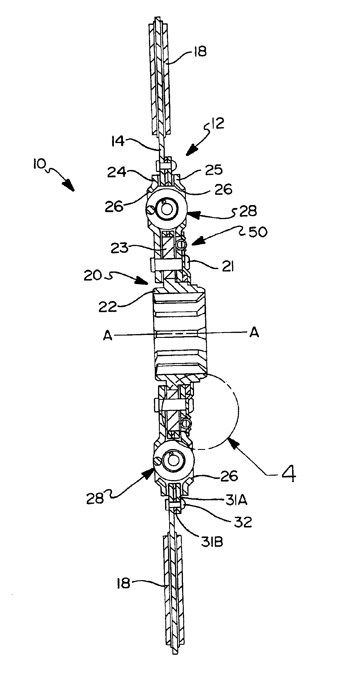
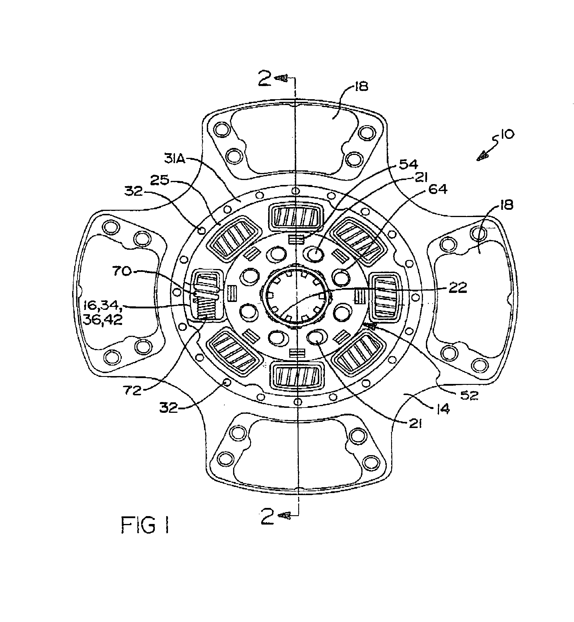
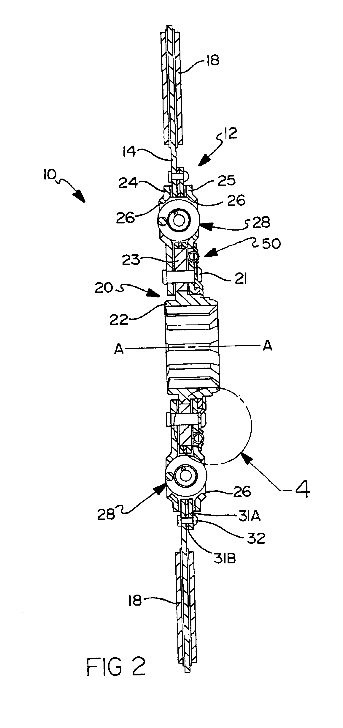
[0015]Referring now to FIGS. 1 and 2, a driven disk 10 according to an embodiment of the present invention is shown. Driven disk 10 includes a rotatable disk assembly 12 having a disk plate 14 that includes a plurality of apertures 16. A number of friction pads 18 are attached to disk plate 14 for frictional engagement between a clutch pressure plate and a driving member, such as an engine flywheel. A hub assembly...


PUM


Abstract

A driven disk is disclosed that includes an inner hub and an outer hub secured to at least one cover plate. The driven disk includes a predamper having a driving element and a driven element. The driving element includes the cover plate and the driven element includes a predamper driven plate fixed to the inner hub. The cover plate includes a number of apertures and the predamper driven plate includes a number of sockets at least partially aligned with the apertures in the cover plate. An energy storage member is disposed within the apertures in the cover plate and the sockets in the predamper driven plate for absorbing torque as a function of relative rotation between the inner hub and the outer hub.

Description

BACKGROUND OF THE INVENTION[0001]1. Field of the Invention[0002]This invention relates in general to friction clutches and in particular to predampers for clutch driven disks.[0003]2. Description of the Related Art[0004]Clutches are well known devices used to selectively connect a source of rotational power to a driven mechanism. For instance, in a vehicle drive-train system, a clutch is used to drivingly connect an engine to a transmission. When the engine is drivingly connected with the transmission by the clutch, vibrations are transmitted through the clutch and into the transmission and other drive-train components, producing undesirable operating conditions, such as gear rattle.[0005]Clutches generally include a clutch hub engaged for rotation with a transmission input shaft and a clutch disk selectively engaged for rotation with the engine flywheel. To reduce the transmission of vibrations, clutches typically employ a plurality of compression damping springs between the clutch...

Claims


Application Information

Patent Timeline
Patent Type & Authority Patents(United States)
IPC IPC(8): F16F15/123F16F15/121
CPCF16F15/1238
Inventor DULANCY, HOLLY B.BASSETT, MICHAEL L.
Owner EATON INTELLIGENT POWER LTD
Why Eureka
Try Eureka