Apparatus and methods for variable sweep body conformal wing with application to projectiles, missiles, and unmanned air vehicles

Inactive Publication Date: 2005-08-02
ZONA TECH
View PDF17 Cites 148 Cited by
  • Summary
  • Abstract
  • Description
  • Claims
  • Application Information

AI Technical Summary

Benefits of technology

[0008]The methods and apparatus according to the present invention addresses many of the shortcomings of the prior art. In accordance with one aspect of the present invention, a UAV apparatus is configured for delivery of a payload, with the UAV having a body, a body-conformal wing, and a control mechanism. The body-conformal wing is configured to variably sweep as a function of the speed, altitude, and/or flight path of the UAV. The body-conformal wing may be configured to form a portion of the outer surface of the UAV when in a closed position. Thu

Problems solved by technology

Unfortunately, UAV range and time for delivery have been limited by, among other things, low aerodynamic efficiency.
As further described below, UAV payload size has also been limited due to the bulk of the devices used to aid in the long range delivery of the UAVs.
Similarly, the un-deployed wings occupy space within the body of the UAV that could otherwise be used for payload.
Furthermore, each of these devices exhibit various degrees of low aerodynamic efficiency, thus limiting the range of delivery of the payload or the range for a surveillance mission or the like.
Moreover, no UAVs have been designed that can be configured to achiev

Method used


Image

  • Apparatus and methods for variable sweep body conformal wing with application to projectiles, missiles, and unmanned air vehicles
  • Apparatus and methods for variable sweep body conformal wing with application to projectiles, missiles, and unmanned air vehicles
  • Apparatus and methods for variable sweep body conformal wing with application to projectiles, missiles, and unmanned air vehicles

Examples


Embodiment Construction

[0025]The present invention may be described herein in terms of various functional components and various method steps. It should be appreciated that such functional components may be realized by any number of structural components, hardware, or software configured to perform the specified functions. For example, the present invention may employ various electronic components and integrated circuits, which are suitably configured for various intended purposes; such as flight control systems.

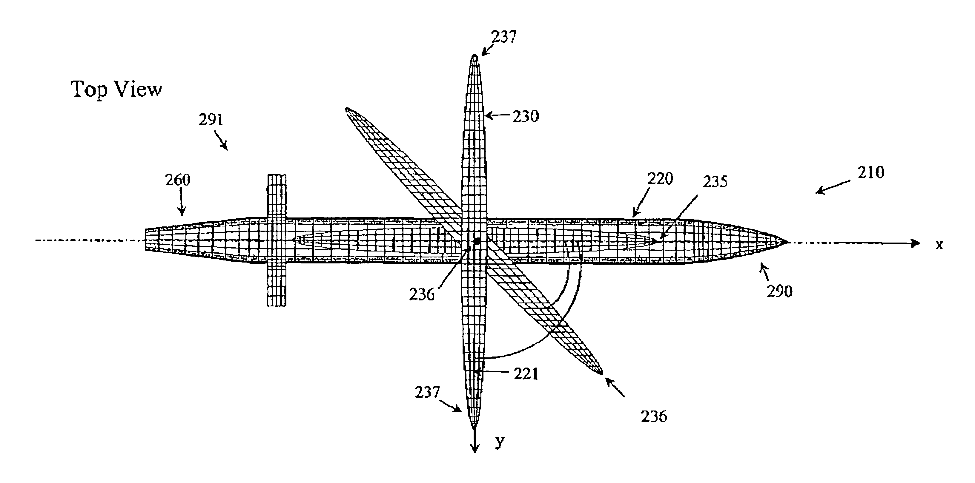
[0026]As used herein, the term UAV refers to any unmanned object that can be gun launched, rocket launched, dropped from a vehicle that is already aloft, or otherwise made to fly through the air over great distances, such as rockets, missiles, projectiles, or any other like un-manned devices. Various aspects of the present invention may be practiced on various types of UAV's regardless of the method of initiating the flight of that UAV or the platform used to initiate that flight. As will be furth...


PUM


Abstract

An unmanned air vehicle (“UAV”) apparatus is configured to have a body and a body-conformal wing. The body-conformal wing is configured to variably sweep from a closed position to a fully deployed position. In the closed position, the body-conformal wing span is aligned with the body axis and in the fully deployed position the body-conformal wing span is perpendicular to the axial direction of the body. Delivery of the UAV comprises the steps of: positioning the span of a body conformal wing in alignment with the axis of the body of the UAV; initiating the flight of the UAV; and adjusting the sweep angle of the body-conformal wing as a function of the current speed, altitude, or attack angle of the UAV, with the adjustment starting at a 0 degree position and varying between a closed position and a fully deployed position. The UAV also has a control mechanism configured to variably adjust the sweep of the body-conformal wing to achieve a high lift over drag ratio through out the flight path of the UAV.

Description

STATEMENT OF GOVERNMENT INVOLVEMENT[0001]This application involves an invention made with United States Government support under SBIR PhaseII entitled “Gun-Launched Projectile / Arizona Glider (AG) Design Concept as an ERGM and Reuseable Launch Munition (RLM) Vehicle,” Contract No. N00178-02-C-1007) awarded by the Navy / NSFS (Naval Surface Warfare Center, Dahlgren Division, Dahlgren, Va. 22448). The Government has certain rights in the invention as described in FAR 52227-11 Patent Rights—Retention by the Contractor (Short Form) June 1997.FIELD OF THE INVENTION[0002]The present invention relates to an unmanned vehicle configured to fly through the air. More particularly, the present invention relates to an apparatus, systems and methods for aerial delivery of an unmanned vehicle having a variable sweep, body-conformal, wing, where the unmanned vehicle is a rocket, projectile, rocket-assist projectile, or other unmanned air delivered or ground launched vehicle.BACKGROUND OF THE INVENTION...

Claims


Application Information

Patent Timeline
IPC IPC(8): B64C9/00B64C1/00B64C30/00B64C3/40B64C3/56B64C5/12B64C39/02B64C39/08B64F1/04F42B10/14F42B10/64
CPCB64C3/40B64C3/56B64C5/12B64C30/00B64C39/024B64C39/028B64C39/08B64F1/04F42B10/14F42B10/64B64C2201/044B64C2201/046B64C2201/048B64C2201/102B64C2201/121B64C2201/125B64C2201/127B64C2201/141B64C2201/146Y02T50/145Y02T50/10B64U50/15B64U50/12B64U50/11B64U30/12B64U2101/15B64U2101/35B64U2201/10B64U2101/30B64U2201/20
Inventor LIU, DANNY D.CHEN, PING-CHIHSARHADDI, DARIUS
Owner ZONA TECH
Why Eureka
Try Eureka