Barbed clip for bone alignment and fixation

Inactive Publication Date: 2005-08-02
BIOPLATE
View PDF15 Cites 32 Cited by
  • Summary
  • Abstract
  • Description
  • Claims
  • Application Information

AI Technical Summary

Benefits of technology

[0009]There is a need for an alignment and fixation device that is

Problems solved by technology

Precise alignment of the two zones can be difficult and the technique can be cumbersome.
Plate and screw systems can be expensive and time consuming to use.
These devices introduce foreign material that is left below the inner cortex, and they do not protect the underlying tissue from compression

Method used


Image

  • Barbed clip for bone alignment and fixation
  • Barbed clip for bone alignment and fixation
  • Barbed clip for bone alignment and fixation

Examples


Embodiment Construction

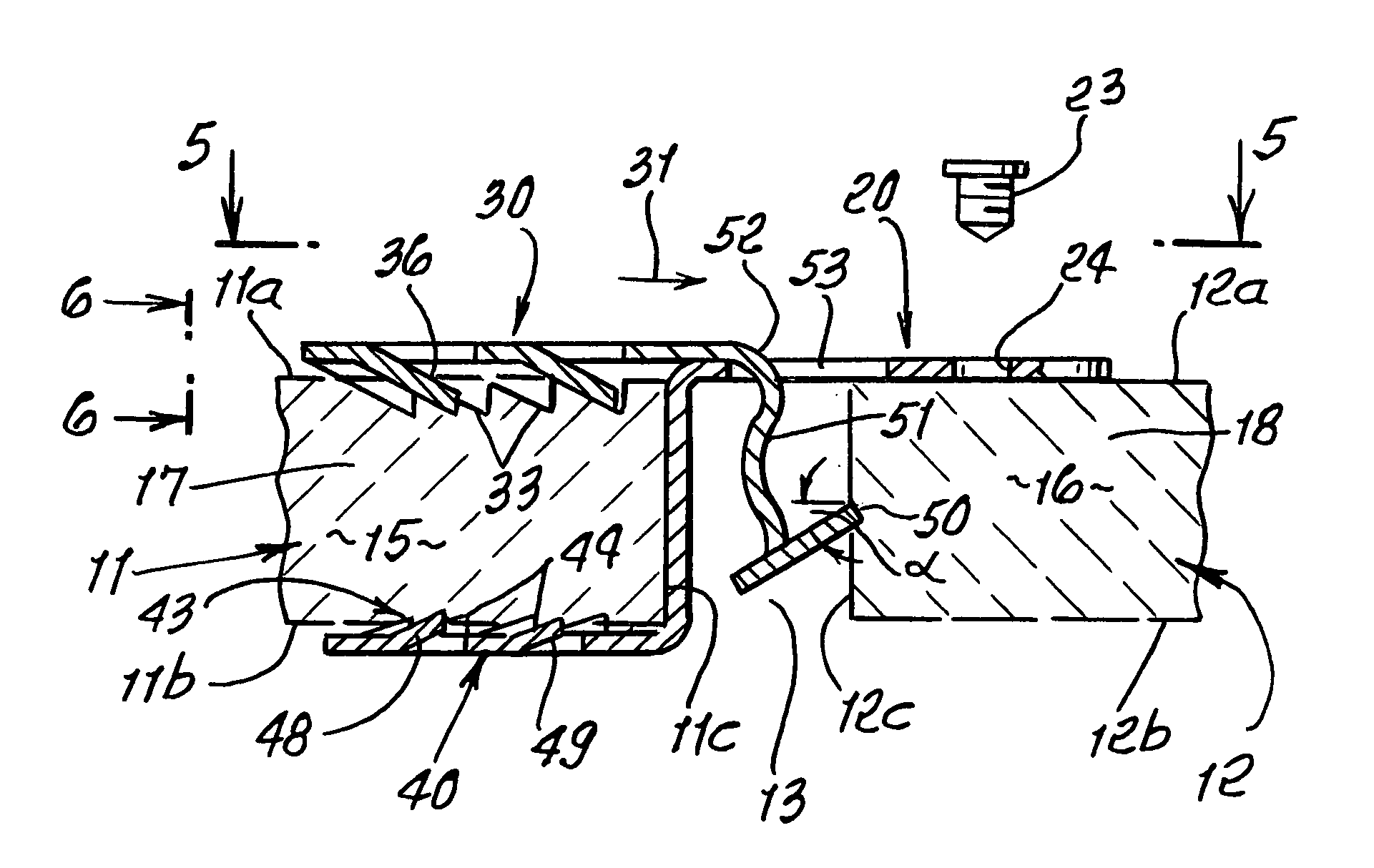
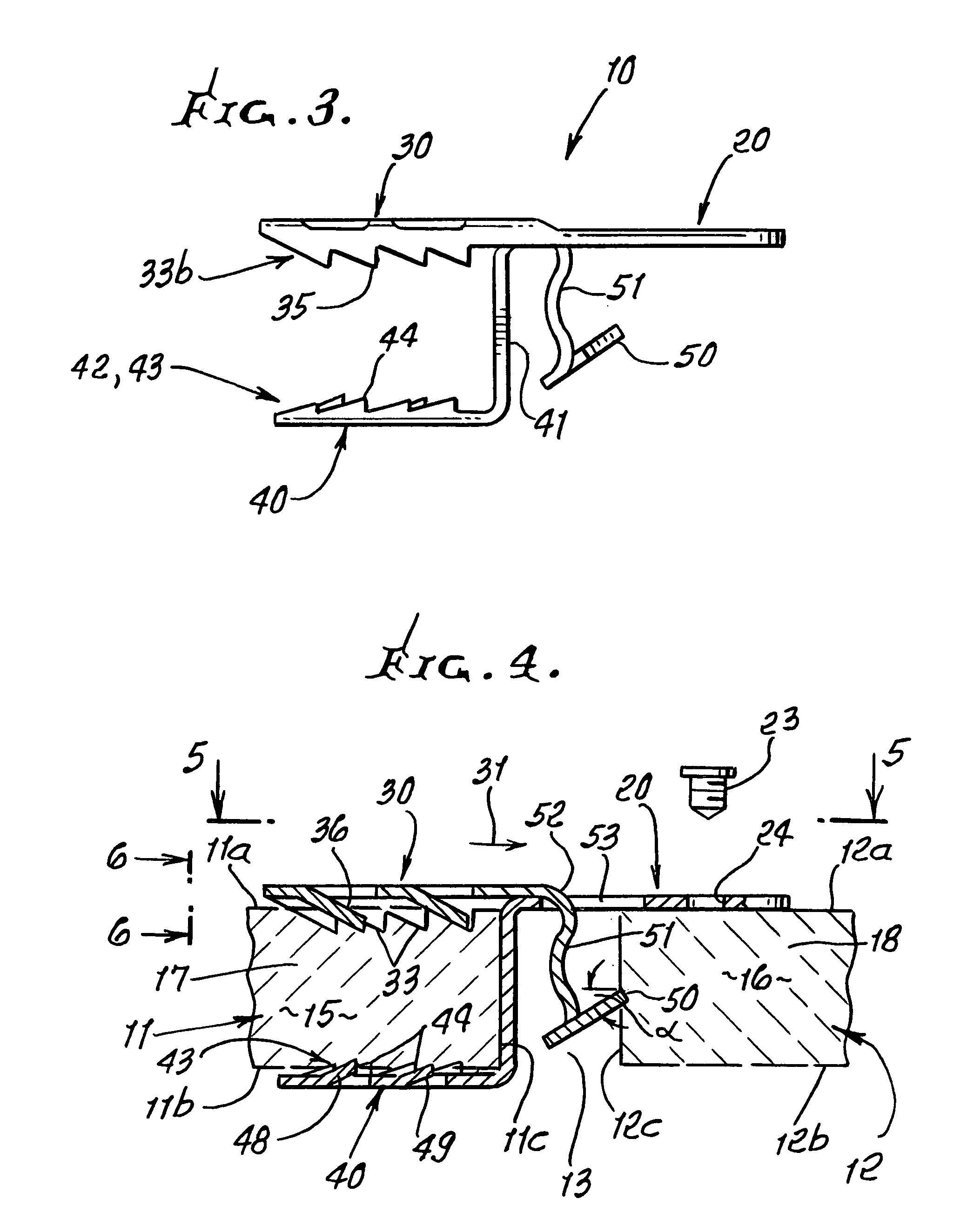
[0028]In FIGS. 1–5, the illustrated clip 10 is configured to interconnect primary and secondary bone zones 11 and 12, having opposed and spaced apart edges 11c and 12c. A cut or gap 13 is formed between the opposed edges of the primary and secondary bone zones. Diploe is shown at 15 between the top and bottom surfaces 11a and 11b of zone 11; and at 16 between the top and bottom surfaces 12a and 12b of zone 12. As also seen in FIG. 4, primary bone zone 11 may be defined by bone flap 17; and secondary bone zone 12 may be defined by skull 18 and its zone extents at 12 opposing zone 11. In the adult, cranial bone or skull averages 7 mm in thickness, but varies between 3 and 12 mm.

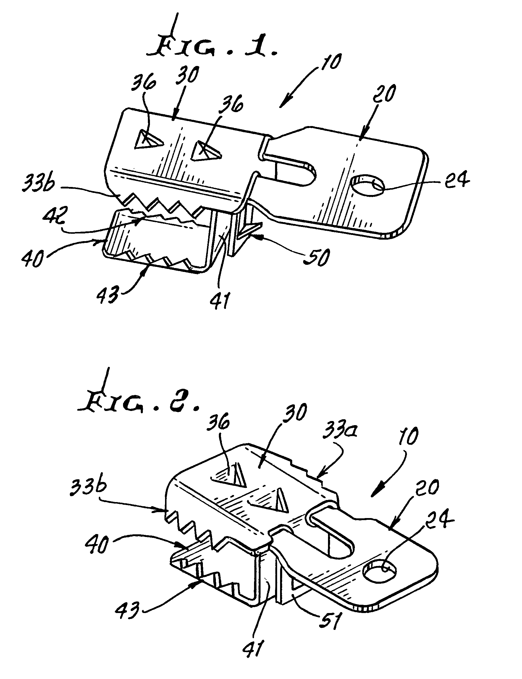
[0029]The clip 10, which is preferably metallic includes the following[0030]a) a first tab 20 to extend proximate and on a surface 12a of the secondary bone zone 12,[0031]b) a second tab 30 associated with the first tab 20, and located to extend proximate and on a surface 11a of the primary bone zone 11,[0032]c...


PUM


Abstract

A clip to interconnect primary and secondary bone zones having edges and surfaces, comprising in combination a first tab to extend proximate a surface of the secondary bone zone; a second tab associated with the first tab, and located to extend proximate a surface of the primary bone zone, the second tab having at least one barb oriented to engage the primary bone to resist displacement of the second tab in a longitudinal direction toward the secondary bone zone.

Description

BACKGROUND OF THE INVENTION[0001]This invention relates generally to the alignment and fixation of bone segments as required for appropriate bone healing, for example after fracture or surgical intervention, and specifically to a device, and the tools needed to install the said device, for the alignment and fixation of cranial bone fragments.[0002]In cases of bone fragmentation where bone fixation is desired, the appropriate alignment of the bone is also a desired result. This is especially true in the cranium, where bone fragmentation can occur as a result of trauma, congenital deformity, or of surgical intervention. In the field of neurosurgery, cranial bone fragments are frequently cut and removed to create defects to allow for access into the cranial cavity and the brain.[0003]The bony cranium is generally regarded to have two surfaces: the outer surface which is characterized by the outer cortex of the bone and is adjacent to the scalp and soft tissue; and the inner surface whi...

Claims


Application Information

Patent Timeline
IPC IPC(8): A61B17/68
CPCA61B17/685A61B17/688
Inventor WELLISZ, TADEUSZ Z.
Owner BIOPLATE
Why Eureka
Try Eureka