
Coiled tubing wellbore cleanout

Inactive Publication Date: 2005-08-02
BJ SERVICES CO
View PDF32 Cites 17 Cited by
  • Summary
  • Abstract
  • Description
  • Claims
  • Application Information

AI Technical Summary

Benefits of technology

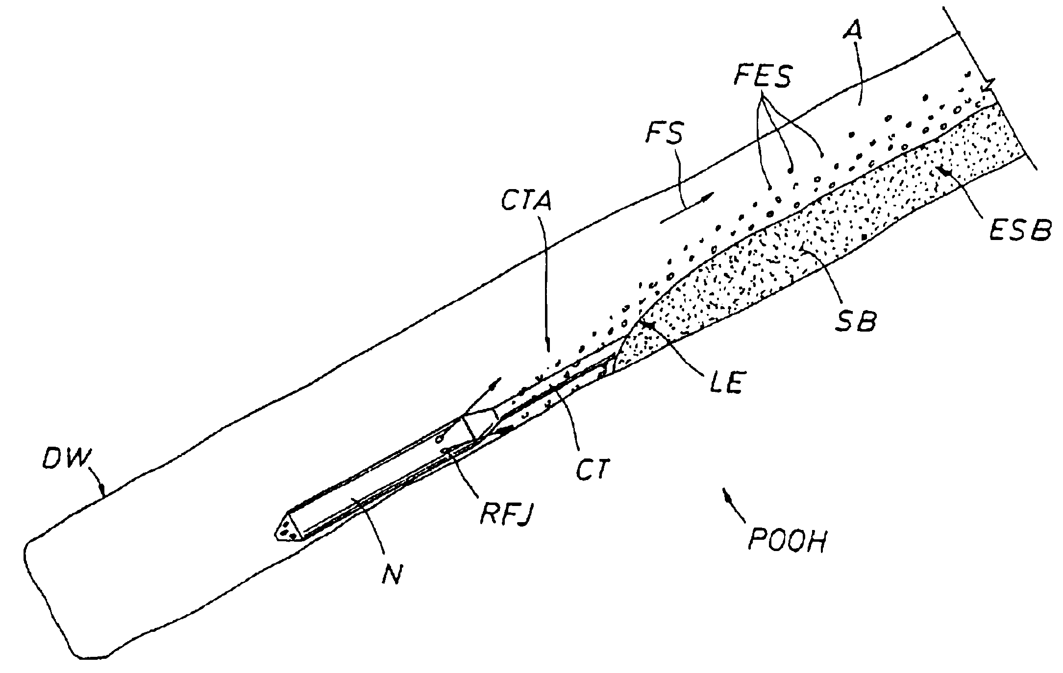
[0016]In preferred embodiments the invention includes tool design and methodology for coiled tubing in vertical, deviated, and horizontal wells. The invention includes running coiled tubing into the well while circulating water, gelled liquids or multiphase fluids using a nozzle with a “high energy” jetting action pointing forwards down the well to stir up the particulate solids and allow the coiled tubing to reach a target depth or bottom of the well. When the bottom or desired depth is reached, the invention includes reversing the jetting direction of the nozzle to point upward (up the wellbore) while circulating water, gelled liquids or multiphase fluids using a low energy vortex nozzle that will create a particle re-entrainment action to enhance agitation of the solids and then entrain the solids in suspension for transport out of the wellbore while pulling the coiled tubing out of the hole. The reverse jetting action along with a controlled pump rate and wiper trip speed can produce a solids transport action which cleans the hole completely by keeping the cuttings in front (upward) of the end of the coiled tubing in continuous agitation. The low energy nozzles have a low pressure drop which allows for higher flow rates which results in improved cleanout efficiency. This method and tool is more efficient than existing methods since the process may be limited to one pass or sweep with the option of resetting the tool for repeated cycles if problems are encountered.

Problems solved by technology

The need for a wiper trip is determined by gauging when a cuttings bed is causing too much drag or friction on the coiled tubing such that it is difficult to lay weight on the bit
A bit and its assembly comprise a costly and elaborate downhole tool for a wiper trip.
To the inventor's best knowledge, however, it has not been known to model two phase flow in these circumstances nor to model the effects of a dynamic wiper trip while jetting.
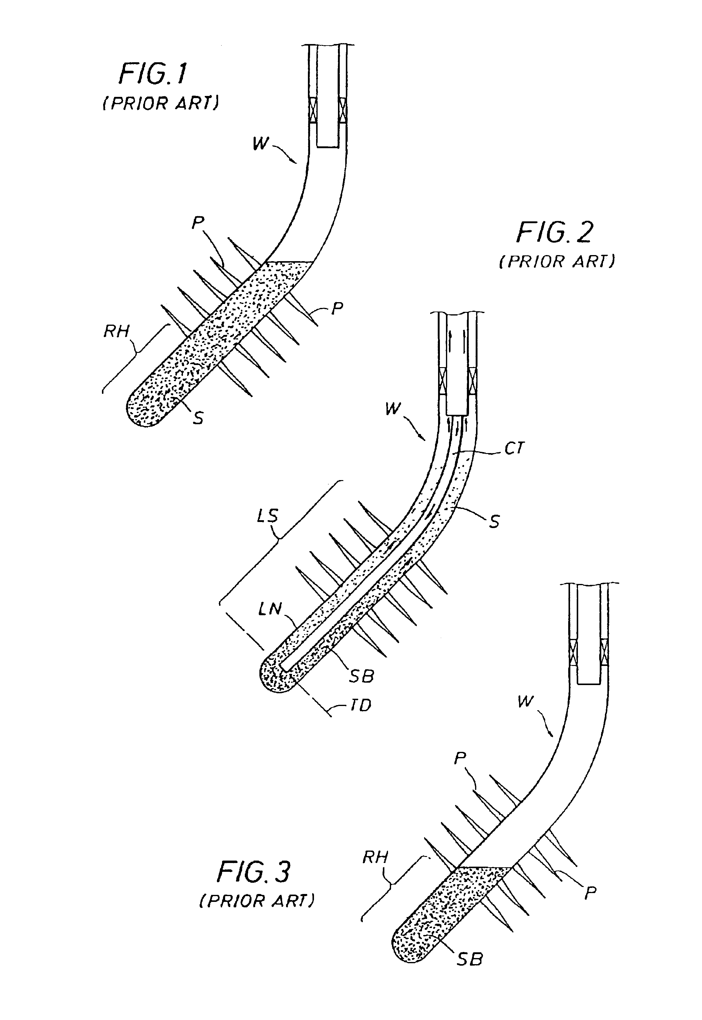
Turning to the well cleanout industry in particular, one problem that has historically faced well owners and operators is the question of whether a well is clean in fact when, during a cleanout, the well is flowing clean with the workover coiled tubing (CT) at target depth (TD).
A second problem is that since many of the so-called “routine” cleanouts are not as simple as might be expected, the usual definition of “clean” is likely to be set by local field experience and may not represent what can or should be achieved.
A third problem has been determining the question of how clean is clean enough.
An ineffective or incomplete well cleanout results in shorter production intervals between cleanouts and increased maintenance.
Unless a well is a vertical hole (<35° deviation) with a generously sized completion assembly and moderate bottom hole pressure, cleanout procedures according to conventional practices are likely to leave significant debris or fill in the hole.

Method used


Image

  • Coiled tubing wellbore cleanout
  • Coiled tubing wellbore cleanout
  • Coiled tubing wellbore cleanout

Examples


example

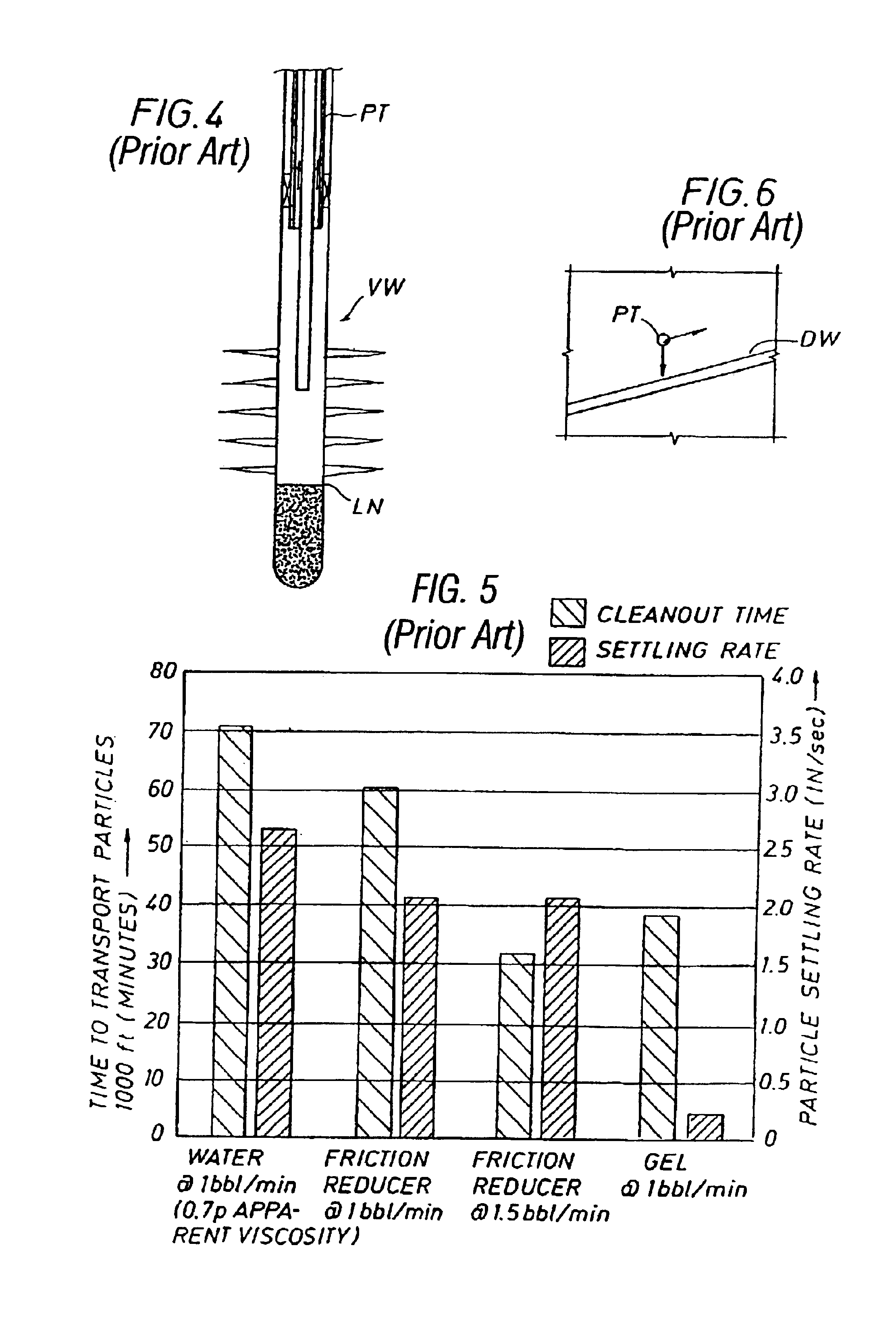
[0097]Wiper trips are a conventional field practice to clean a hole of sand in cleanout operations. A wiper trip can be defined as the movement of the end of coiled tubing in and out of the hole, at least a certain distance. In order to clean solids out of the wellbore, a proper wiper trip speed should be selected based on operational conditions. There is no previously published information related to the selection of the wiper trip speed. In this study, numerous laboratory tests were conducted to investigate wiper trip hole cleaning and how hole cleaning efficiency is influenced by solids transport parameters such as; a) nozzle type, b) particle size, c) fluid type, d) deviation angle, e) multi-phase flow effect.

The results indicate the following:

[0098]1. Compared with stationary circulation hole cleaning, the use of the wiper trip produces a more efficient cleanout.[0099]2. For a given operational condition, there is an optimum wiper trip speed at which the solids can be completel...


PUM


Abstract

Method and apparatus for substantially cleaning fill from a borehole, variously including in preferred embodiments disturbing particulate solids of fill while RIH, entraining particulates while POOH, jetting downhole while RIH and jetting uphole while POOH, and controlling at least one of a pump rate regime or a POOH rate regime.

Description

CROSS-REFERENCE TO RELATED APPLICATIONS[0001]This application is a continuation of U.S. patent application Ser. No. 09 / 799,990, filed Mar. 6. 2001, now U.S. Pat. No. 6,607,607 entitled COILED TUBING WELLBORE CLEANOUT by Scott A. Walker, Jeff Li and Graham Wilde, which claimed priority based on provisional application Ser. No. 60 / 200,241 filed Apr. 28, 2000.FIELD OF THE INVENTION[0002]This invention is related to cleaning a wellbore of fill, and more particularly, to cleaning an oil / gas wellbore of substantial fill using coiled tubing.BACKGROUND OF THE INVENTION[0003]Solutions exist to an analogous problem in a related field, the problem of cuttings beds in the field of coiled tubing drilling in deviated wells, a field employing different equipment in different circumstances. The solutions are similar but have important distinctions with regard to the instant invention. Some, though not all, practitioners when drilling with coiled tubing (CT) in deviated wells cleanout cutting beds t...

Claims


Application Information

Patent Timeline
Patent Type & Authority Patents(United States)
IPC IPC(8): E21B21/00E21B44/00E21B41/00B08B9/00B08B9/04E21B37/00
CPCB08B9/0433E21B21/00E21B37/00E21B41/0078E21B44/00
Inventor WALKER, SCOTT A.LI, JEFFWILDE, GRAHAM
Owner BJ SERVICES CO
Learn More