
Separation column devices and fabrication methods

a technology of separation column and fabrication method, which is applied in the direction of microstructural device, microstructural technology, chemical/physical process, etc., can solve the problems of limiting the utility of conventional packing methods such as slow and difficult, and foregoing packing methods

Inactive Publication Date: 2005-08-02
AGILENT TECH INC
View PDF91 Cites 110 Cited by
  • Summary
  • Abstract
  • Description
  • Claims
  • Application Information

AI Technical Summary

Benefits of technology

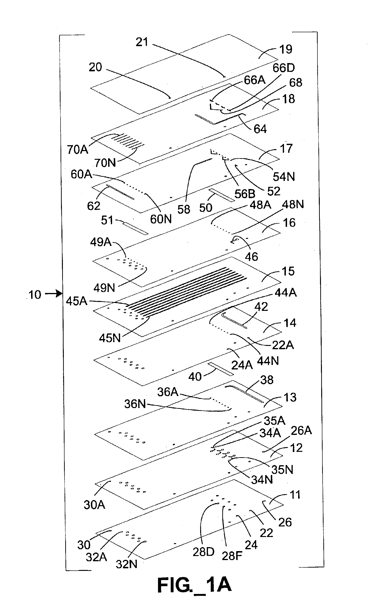
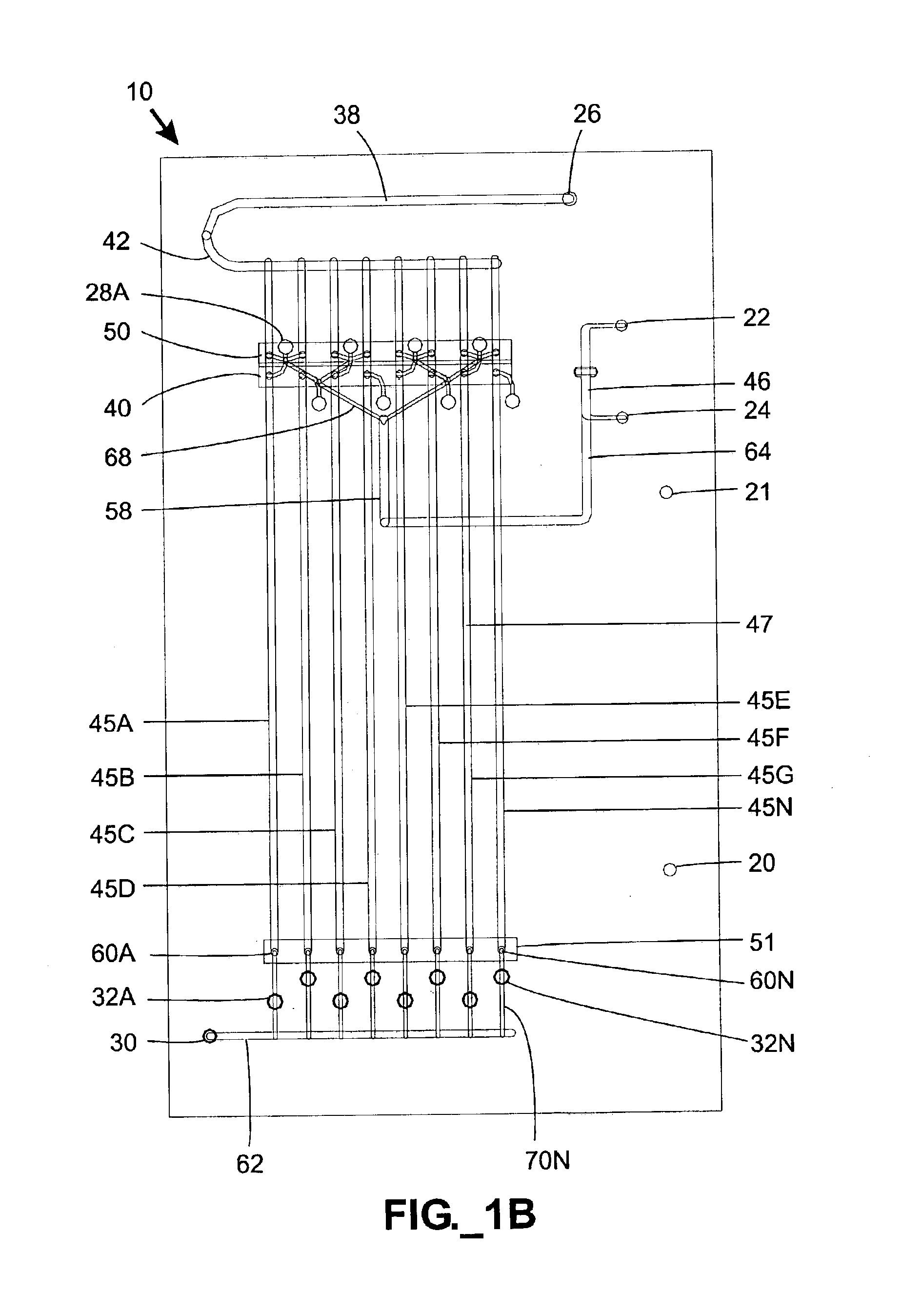
The present invention relates to the fabrication of separation columns, such as chromatography columns, for separating chemical or biological species. The invention provides improved column packing methods that are faster, more efficient, and can be used for packing multiple separation columns simultaneously. The invention also provides methods for fabricating microfluidic separation devices with multiple columns and can scale up for large-scale production. The technical effects of the invention include improved efficiency and speed in the packing of separation columns and the ability to pack multiple columns simultaneously or on a single device.

Problems solved by technology

Separation columns may be packed in several different ways, although conventional methods for packing such columns are typically slow and difficult.
The foregoing packing methods have drawbacks that limit their utility.
To begin with, such methods are relatively slow and inefficient.
These steps are labor-intensive, and the presence of additional fittings presents potential leakage problems during operation.
Additionally, conventional slurry-packing methods are plagued with notorious blockage problems, especially when applied to small-bore columns such as capillaries.
Conventional packing methods, however, are not capable of packing multiple separation columns simultaneously.

Method used


Image

  • Separation column devices and fabrication methods
  • Separation column devices and fabrication methods
  • Separation column devices and fabrication methods

Examples


Embodiment Construction

Definitions

[0035]The term “column” as used herein refers to a region of a fluidic device containing stationary phase material, typically including packed particulate matter. In microfluidic devices described herein, the term “column” is used synonymously with a packed separation channel.

[0036]The term “microfluidic” as used herein refers to structures or devices through which one or more fluids are capable of being passed or directed and having at least one dimension less than about 500 microns.

[0037]The term “pressure vessel” as used herein refers to a vessel that is substantially sealed against unintended leakage and is capable of being pressurized to a pressure that is significantly greater-than-atmospheric pressure.

[0038]The term “slurry” as used herein refers to a mixture of particulate matter and a solvent, preferably a suspension of particles in a solvent.

[0039]The term “stencil” as used herein refers to a material layer or sheet that is preferably substantially planar throug...


PUM

PropertyMeasurementUnit
pressureaaaaaaaaaa
pressureaaaaaaaaaa
lengthaaaaaaaaaa

Abstract

Pressure-driven microfluidic separation devices, such as may be used for performing high performance liquid chromatography, are provided. Multiple separation columns may be defined in a single device and packed with stationary phase material retained by porous frits. One or more splitters may be provided to distribute slurry and / or mobile phase among multiple separation columns. In one embodiment, separation devices are substantially planar and fabricated with multiple device layers. Systems and methods employing slurry for packing separation devices are also provided.

Description

STATEMENT OF RELATED APPLICATION(S)[0001]This application claims benefit of two commonly assigned U.S. Provisional Patent Applications, Ser. No. 60 / 357,683 filed Feb. 13, 2002 and Ser. No. 60 / 415,896 filed Oct. 3, 2002.FIELD OF THE INVENTION[0002]The present invention relates to the fabrication of separation columns such as may be used for separating chemical or biological species.BACKGROUND OF THE INVENTION[0003]Chemical and biological separations are routinely performed in various industrial and academic settings. One technique for performing such separations, chromatography, encompasses a number of methods that are used for separating closely related components of mixtures. In fact, chromatography has many applications including separation, identification, purification, and quantification of compounds within various mixtures. Chromatography is a physical method of separation wherein components typically partition between two phases: a stationary phase and a mobile phase. Sample c...

Claims


Application Information

Patent Timeline
Patent Type & Authority Patents(United States)
IPC IPC(8): B01L3/00B29C65/00G01N30/00G01N30/60G01N30/56B01D15/08B01F13/00B01J19/00B01J20/281B01J20/283B01J20/285G01N30/26G01N30/46G01N30/74G01N30/78G01N30/88
CPCB01F13/0059B01J19/0093B01L3/502753B29C66/02B81C3/008G01N30/6095B01F15/0264B29C66/727B01L3/502707B01L3/50273B01L3/502761B01L2300/0681B01L2300/0864B01L2300/0867B01L2300/0874B01L2300/0887B01L2300/14B01L2400/0406B01L2400/0688B29C66/026B29K2023/00B29K2023/12B29L2031/756B81B2201/058G01N2030/565G01N2030/6056B29C2035/0827B29C65/02B29C66/71B01F33/30B01F35/7182
Inventor HOBBS, STEVEN E.GREGORI, MATTHEW M.KARP, CHRISTOPH D.KOEHLER, JEFFREY A.PATEL, PAREN P.COVINGTON, JOSEPH F.
Owner AGILENT TECH INC
Learn More