Electromagnetic relay

a technology of electromagnetic relay and relay, which is applied in the direction of relays, circuit breaking switches, circuit breaking switches for excess current, etc., can solve the problems of large and heavy movable pieces, difficult to cause the indicator to operate smoothly, etc., to reduce the weight of the coil block, prevent the increase in the size of the card, and reduce the power consumption. effect of the coil block

Active Publication Date: 2005-08-02
ORMON CORP
View PDF6 Cites 31 Cited by
  • Summary
  • Abstract
  • Description
  • Claims
  • Application Information

AI Technical Summary

Benefits of technology

[0007]Thus, it is an object of the present invention to provide an electromagnetic relay which can reduce power consumption in a coil block and cause an indicator to operate smoothly.
[0009]With this structure, the card and the indicator can be arranged in positions closest to the coil block, and an increase in a size of the card can be prevented to reduce a weight thereof. As a result, it becomes possible to reduce power consumption in the coil block to make operations of the card and the indicator smooth.
[0010]It is preferable that an insulation wall is formed between the coil block and the contact switching mechanism, and release portions for avoiding interference at the time of rotation of the indicator are formed in the insulation wall because it becomes possible to secure a desired insulation distance between the coil block and the contact switching mechanism while effectively utilizing a limited space.
[0011]It is preferable that bearing portions are formed on sides of the insulation wall, and the indicator has an elastically deformable structure including pivots, which rotatably engages in the bearing portions, because attachment work of the indicator can be performed easily, and it is possible to make an operation of the indicator smooth.
[0012]It is preferable that the indicator includes an indication piece at an upper end thereof, and the case includes a projected portion, which forms a space in which the indication piece is movable, in a central part on an upper surface thereof because it becomes possible to locate an indication portion of the indicator in a position excellent in visibility.

Problems solved by technology

Consequently, large and heavy movable pieces have to be used in order to drive the indicator.
As a result, it is difficult to cause the indicator to operate smoothly while reducing power consumption in the coil block.

Method used


Image

  • Electromagnetic relay
  • Electromagnetic relay
  • Electromagnetic relay

Examples


Embodiment Construction

[0038]Embodiments in accordance with the present invention will be hereinafter described with reference to the accompanying drawings.

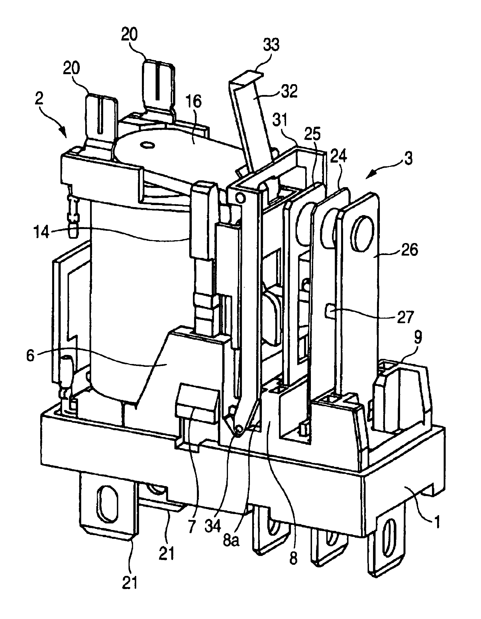
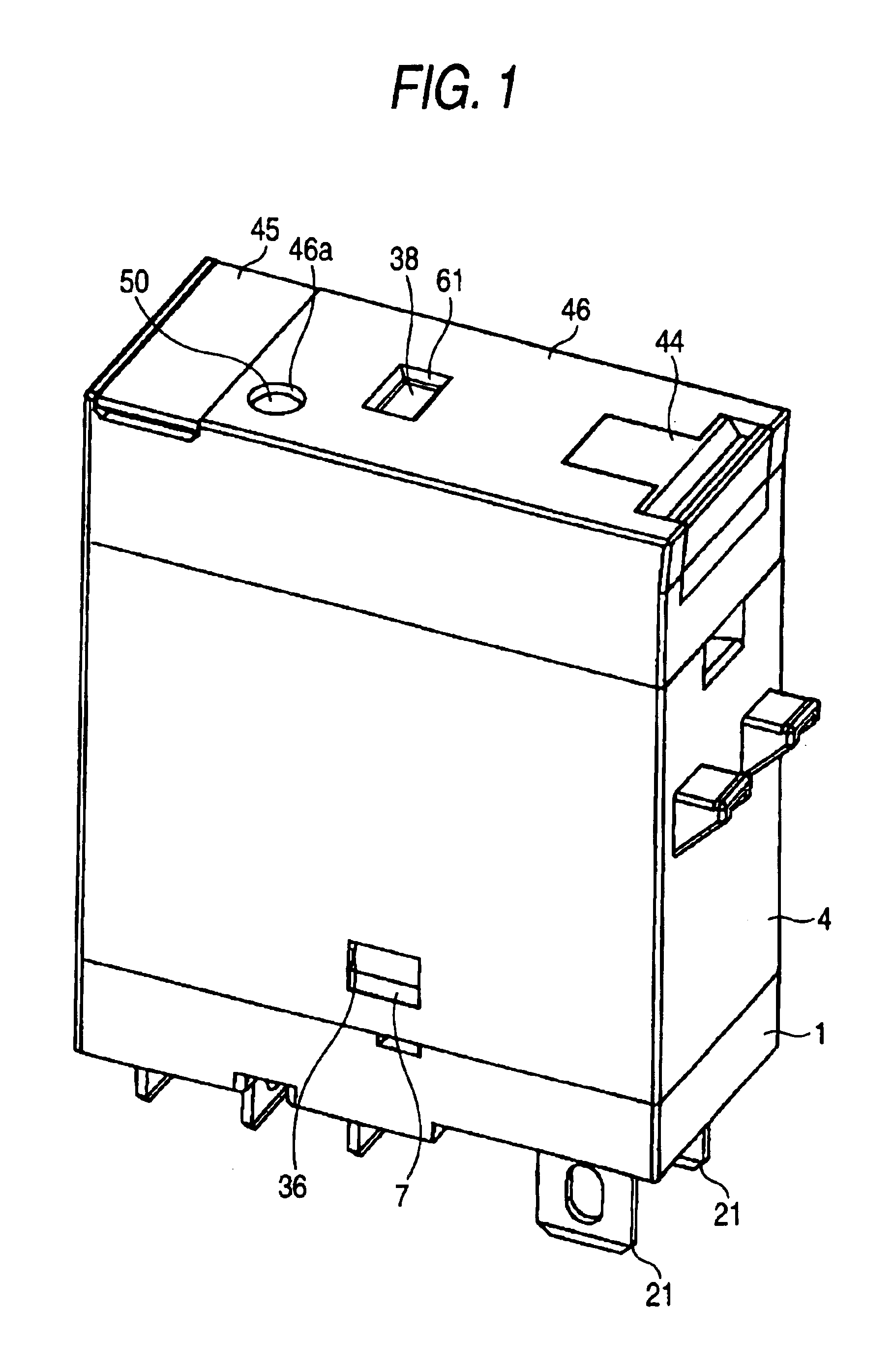
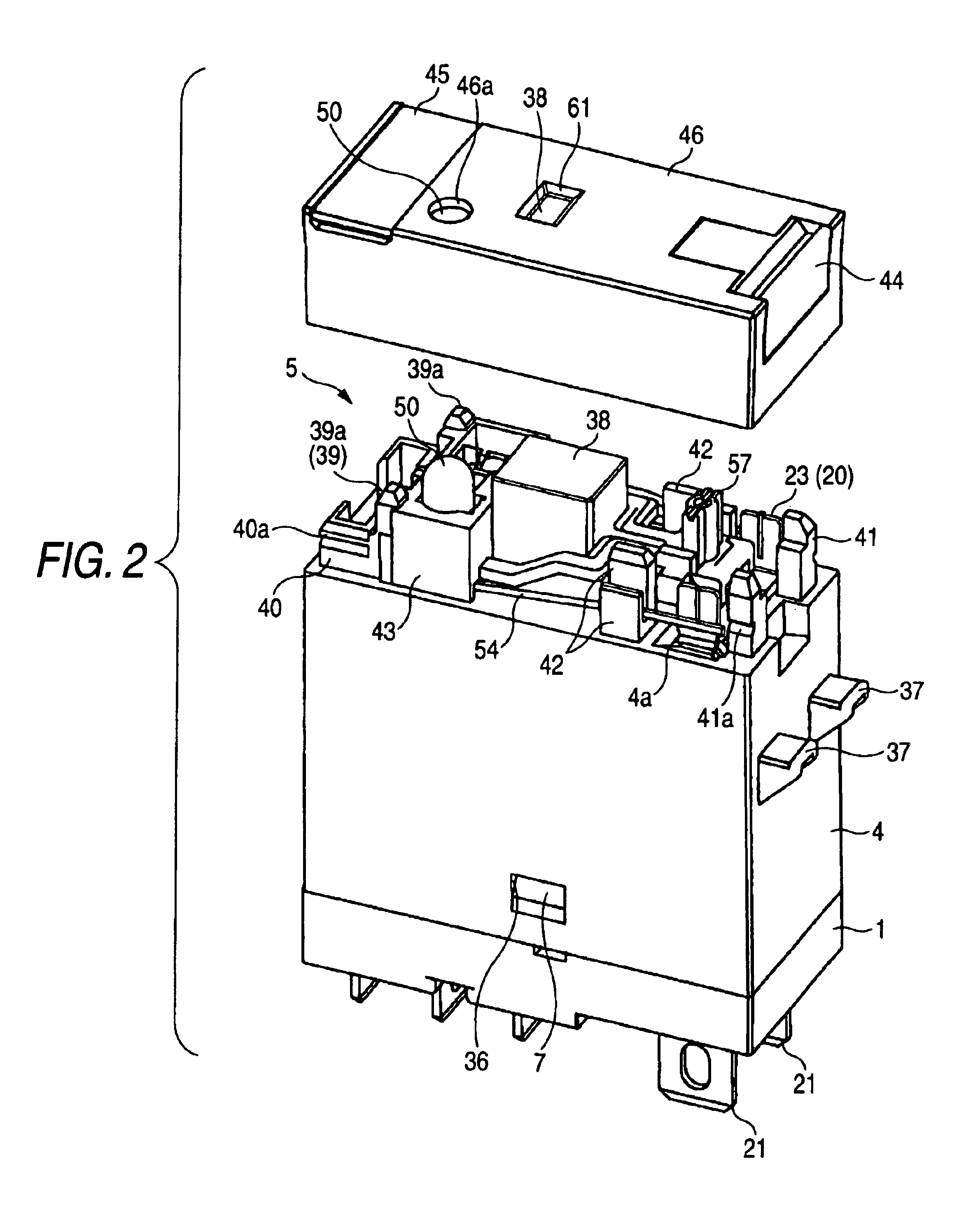
[0039]FIGS. 1 to 4 show an electromagnetic relay in accordance with an embodiment of the present invention. This electromagnetic relay generally has a structure in which a coil block 2 and a contact switching mechanism 3 are provided on a base plate 1, a case 4 is covered over the base plate 1, and an indication block 5 is arranged on an upper surface of the case 4.

[0040]As shown in FIGS. 3 and 5, the base plate 1 is divided into a first area, in which the coil block 2 is arranged, and a second area, in which the contact switching mechanism 3 is arranged, by a first insulation wall 6. A locking projected portion 7 is formed in a side part of the first insulation wall 6. The locking projected portion 7 locks into a locking hole 36 of the case 4 to be described later, whereby the case 4 is attached to the base plate 1. In addition, the second area is div...


PUM


Abstract

An electromagnetic relay, which reduces power consumption in a coil block and causes an indicator to operate smoothly, is provided. A coil block and a contact switching mechanism are provided on a base plate, a case is covered over the base plate, the coil block is excited and demagnetized to rotate a movable iron piece, and a movable contact piece is operated via a card, whereby a contact is opened and closed. An indicator, which operates following movement of the card by the rotation of the movable iron piece, is provided between the coil block and the contact switching mechanism.

Description

CROSS-REFERENCE TO RELATED APPLICATIONS[0001]This application claims priority from Japanese Application JP2003-120310, filed on Apr. 24, 2003.BACKGROUND OF THE INVENTION[0002]1. Field of the Invention[0003]The present invention relates to an electromagnetic relay.[0004]2. Description of the Related Art[0005]Conventionally, as an electromagnetic relay, there is one which is adapted to drive a movable piece with excitation and demagnetization of a coil block to operate an indicator (e.g., see WO01 / 48777 A1).[0006]However, in the electromagnetic relay, the indicator is arranged at one end of a base plate remote from the coil block. Consequently, large and heavy movable pieces have to be used in order to drive the indicator. As a result, it is difficult to cause the indicator to operate smoothly while reducing power consumption in the coil block.SUMMARY OF THE INVENTION[0007]Thus, it is an object of the present invention to provide an electromagnetic relay which can reduce power consump...

Claims


Application Information

Patent Timeline
Patent Type & Authority Patents(United States)
IPC IPC(8): H01H50/08H01H50/00H01H50/02H01H50/06H01H50/26
CPCH01H50/08H01H50/021H01H50/06H01H50/326H01H50/443H01H2050/046
Inventor SARUWATARI, YOJIROYANO, KEISUKEFURUSYO, SHINICHIFUJIWARA, TETSUYAMINOWA, RYOTA
Owner ORMON CORP
Why Eureka
Try Eureka