Cooling system for magnetic field generating device

a magnetic field and cooling system technology, applied in the direction of magnets, electromagnets without armatures, magnetic fields, etc., can solve the problems of affecting the efficiency of airflow

Inactive Publication Date: 2005-08-02
EMF THERAPEUTICS
View PDF6 Cites 5 Cited by
  • Summary
  • Abstract
  • Description
  • Claims
  • Application Information

AI Technical Summary

Benefits of technology

[0016]A plurality of optional spacers are preferably provided on the inside surface of the perforated and non-perforated panels. The spacers help retain the coil in its installed, wound position and further provide a space between the coil and the various panels to allow for more efficient airflow across and over the wound conductor.

Problems solved by technology

The ability of electric current to travel through a conductor is impeded by the inherent resistance of the material composition of the conductor.
The complex magnetic field generating device found in the Davidson patent is known to generate substantial amounts of heat during use.
The air space between the raceway cover and the current carrying coil of the Davidson apparatus is deemed to be inadequate by itself to allow proper cooling of the coil during use at various given amperage levels.
While it is believed to be superior in its cooling ability as compared to the Davidson device, it, too, has a tendency to generate significant amounts of heat during use at various elevated amperage levels.

Method used


Image

  • Cooling system for magnetic field generating device
  • Cooling system for magnetic field generating device
  • Cooling system for magnetic field generating device

Examples


Embodiment Construction

[0046]With reference to FIGS. 1 through 3, an embodiment of the present invention is designated generally by the reference numeral 10. Embodiment 10 includes a central passageway 12, a frame assembly designated generally by the reference numeral 14, a frame interior 16 onto which a plurality of permanent magnets 18 are positioned in side-by-side axis parallel relationship and conductor 20 is wound to form a coil. It should be noted that the permanent magnets 18 are optional and may be excluded from an operable embodiment of the present invention. In addition, the permanent magnets may be in place in position and the coil 20 eliminated to provide a suitable embodiment of the present invention. However, with respect to the heat removal characteristics, the heat removal problems to which the supplementary cooling system described herein below is provided mainly to remove the heat generated by the coil 20 during operation.

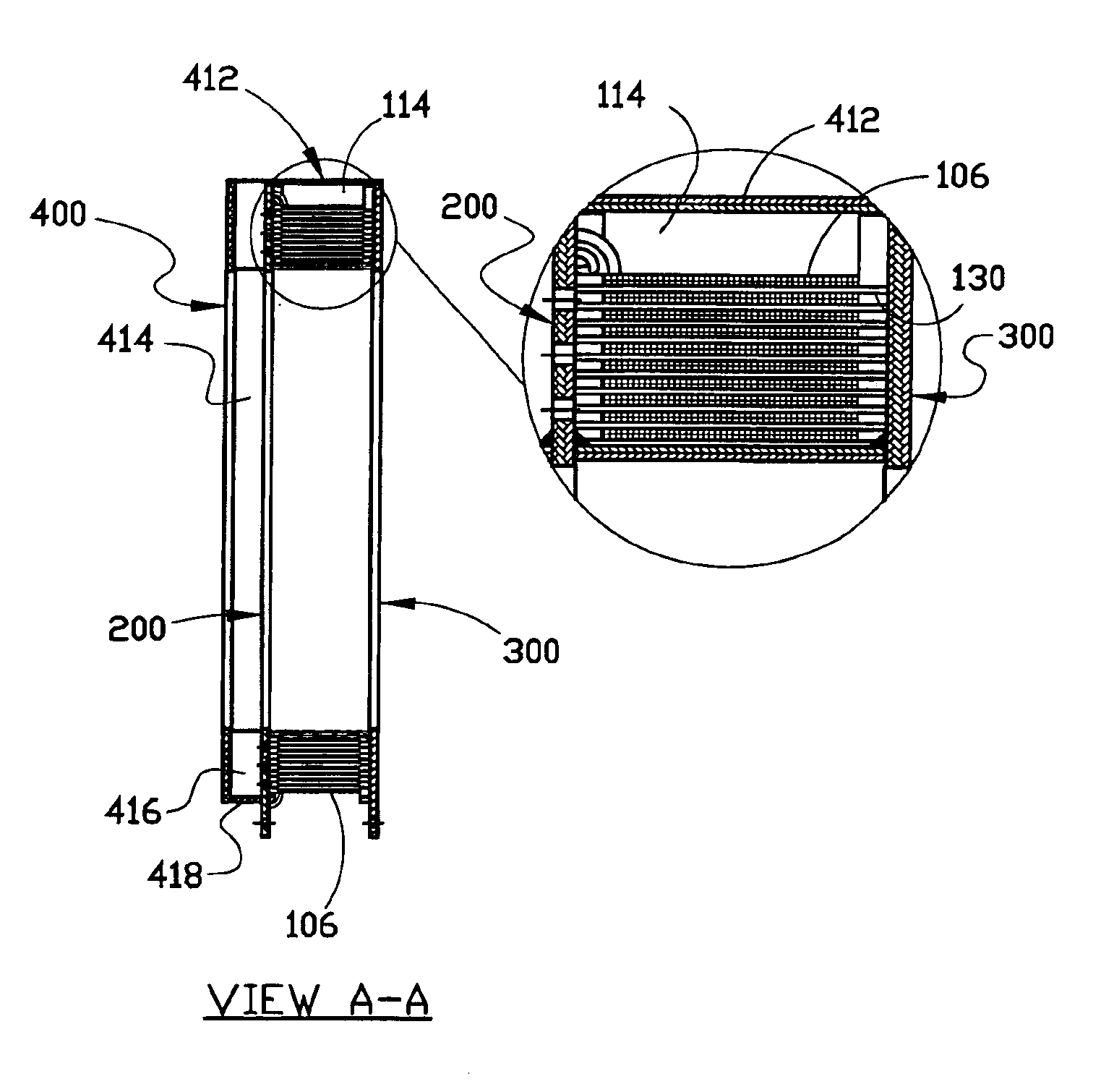
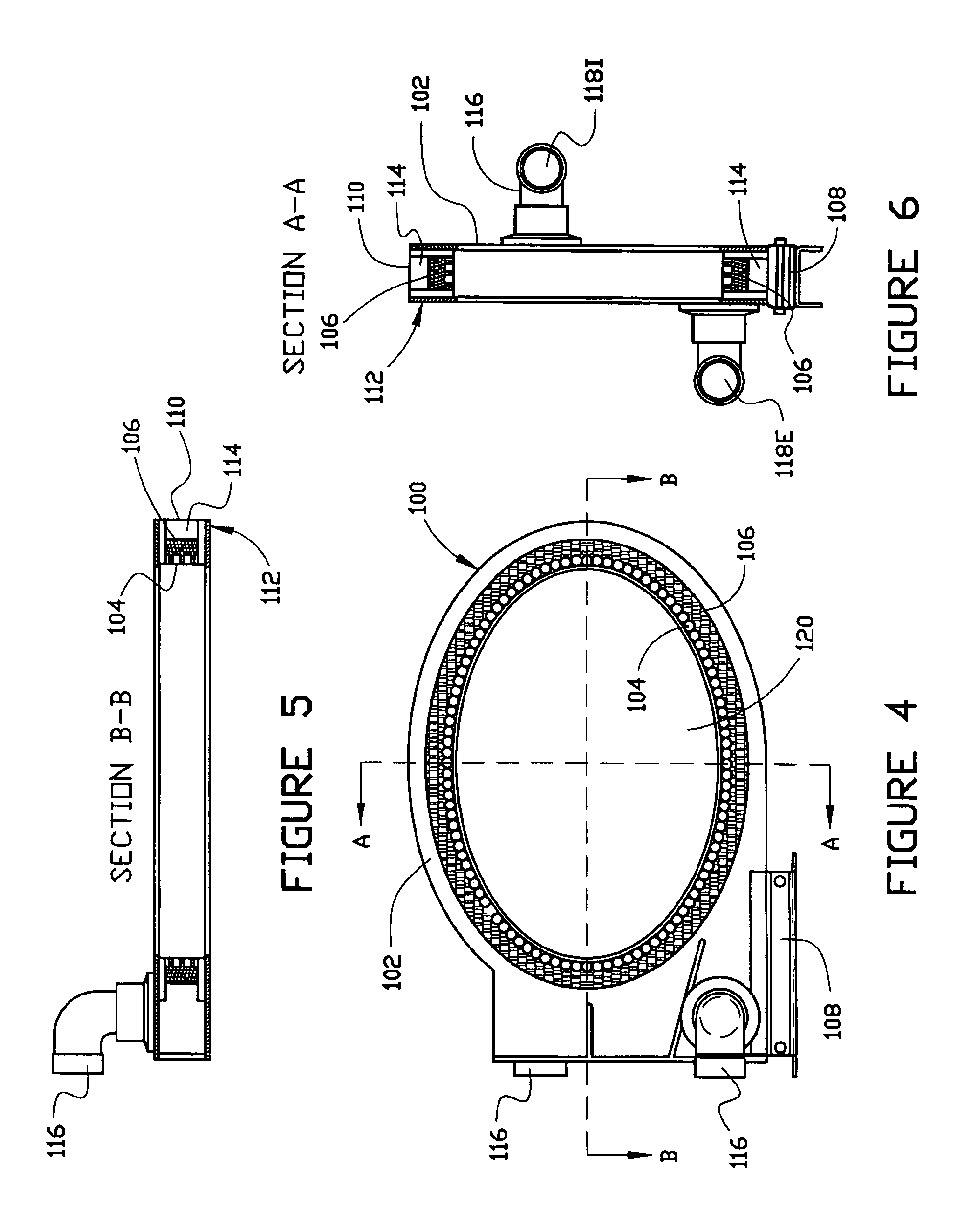
[0047]With reference to FIGS. 4 through 6, an alternate embodimen...


PUM

PropertyMeasurementUnit
magnetic fieldaaaaaaaaaa
electrically conductingaaaaaaaaaa
elliptical shapeaaaaaaaaaa

Abstract

A magnetic field generating device comprising a frame about which a current carrying coil of conductor is wound. The frame preferably includes spaced-apart side panels and an auxiliary supplementary cooling system panel. Each of the panels is configured with a plurality of spacers and / or perforations to facilitate and encourage the movement of air within the apparatus. The spacers are preferably provided on the interior surfaces of the primary panels to maintain the coil winding in a centered position therewith. Spacers may also be interpositioned between the various layers of the coil itself to enable airflow into and around the various coil layers. Of course, in the alternate embodiment a plurality of coils may be provided such that each individual layers or combination thereof may comprise an individual coil. The preferred frame includes a perforated panel, a substantially non-perforated panel, and a auxiliary supplementary cooling system panel to enable the airflow from within the air space itself interpositioned between the perforated panel and substantially non-perforated panel into the air space established by the auxiliary supplementary cooling system panel and the perforated panel prior to exit and expulsion to the outer atmosphere.

Description

CROSS-REFERENCE TO RELATED APPLICATION[0001]This application is a continuation of the application entitled COOLING SYSTEM FOR MAGNETIC FIELD GENERATING DEVICE, which was filed on Apr. 28, 2000, now abandoned and assigned a Ser. No. 09 / 560,846.BACKGROUND OF THE INVENTION[0002]1. Field of the Invention[0003]The present invention relates generally to magnetic field generating devices but more particularly to such devices incorporating a current carrying field coil which is known to generate heat during use, and, therefore, create a need for a cooling system and associated ductwork to remove unwanted heat from the system.[0004]2. Description of the Related Art[0005]It is well known that current-carrying wires have a tendency to generate heat due to the inherent resistance of the wire to carry the load current as well as other phenomenon known as “hysteresis”. The ability of electric current to travel through a conductor is impeded by the inherent resistance of the material composition o...

Claims


Application Information

Patent Timeline
Patent Type & Authority Patents(United States)
IPC IPC(8): H01F7/20H01F27/32H01F27/08
CPCH01F7/202H01F27/085H01F27/322
Inventor BOULDIN, FLOYD E.WILLIAMS, C. DOUGLASBOULDIN, DWIGHT
Owner EMF THERAPEUTICS
Why Eureka
Try Eureka