Information recording medium

a technology of information recording and information, applied in the direction of recording signal processing, instruments, disposition/mounting of heads, etc., can solve the problems of increased chance, copyright infringement, and operation reversely from read only to recording/reproducing area also defectiv

Inactive Publication Date: 2005-08-02
JVC KENWOOD CORP A CORP OF JAPAN
View PDF8 Cites 34 Cited by
  • Summary
  • Abstract
  • Description
  • Claims
  • Application Information

AI Technical Summary

Benefits of technology

[0011]Accordingly, in consideration of the above-mentioned problems of the prior art, an object of the present invention is to provide an information recording medium, which can solve the problem mentioned above.

Problems solved by technology

A problem arises along with a trend toward multimedia causing to increase a chance such that copyright is infringed by using an electronic means.
However, there is existed a following problem of the prior art mentioned above.
A defect has occurred when an information recording medium formed with microscopic patterns shown in FIG. 2 has been loaded in various recording / reproducing apparatuses, which are currently available in a market, and operated.
Further, an operation traversing reversely from the read only area to the recording / reproducing area is also defective.
In other words, firstly, the problem is caused by that forming the read only area in the depth of d1=λ / 4n results a push-pull signal output in zero.
Further, as a second problem, output difference between a push-pull signal output of the read only area and a push-pull signal output of the recording / reproducing area is large, so that a servo system of the recording / reproducing apparatus can not follow properly.

Method used


Image

  • Information recording medium
  • Information recording medium
  • Information recording medium

Examples


first embodiment

[First embodiment]

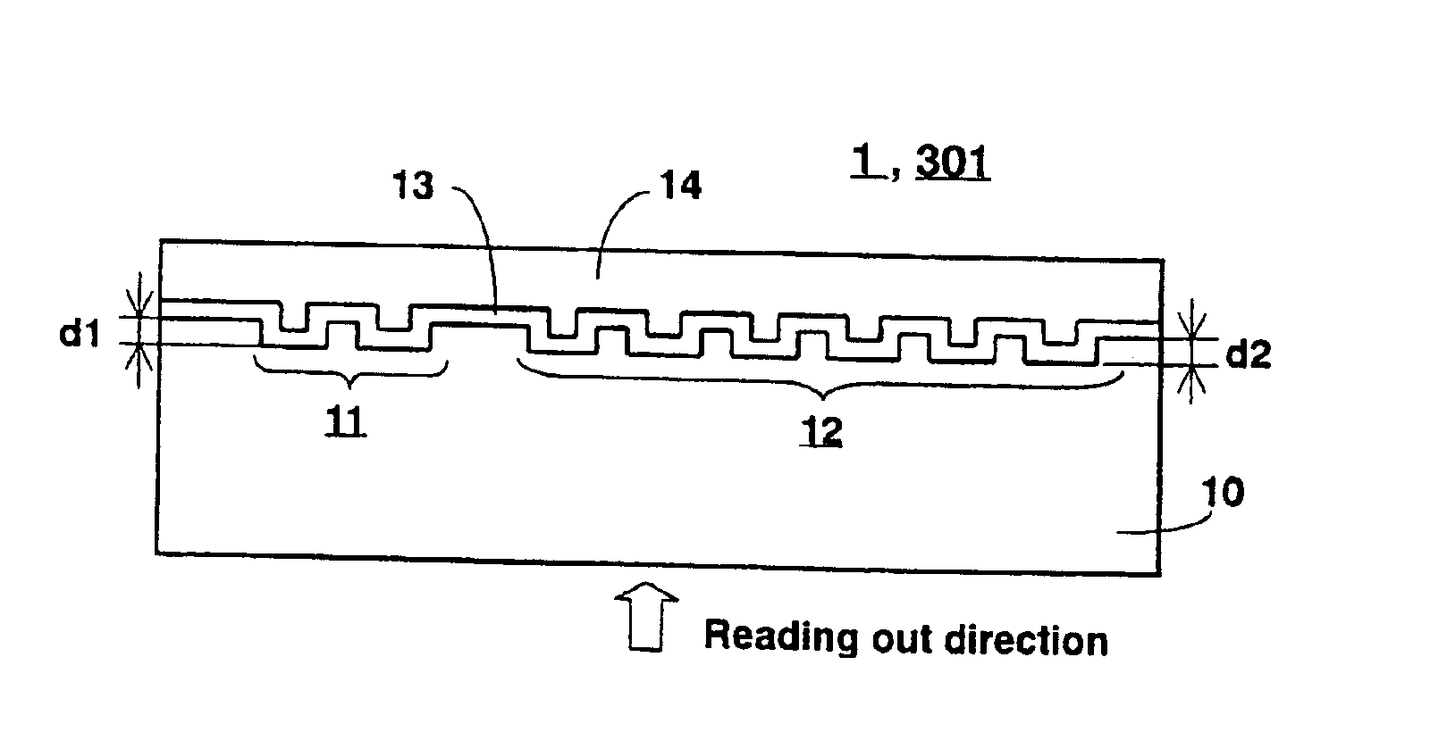
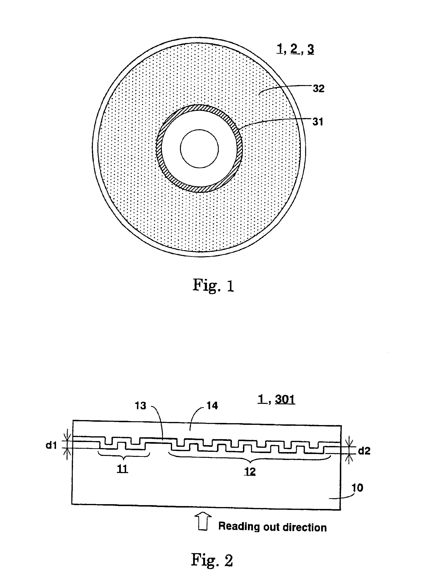
[0065]FIG. 1 is a plan view of an information recording medium in a disk shape according to an embodiment of the present invention.

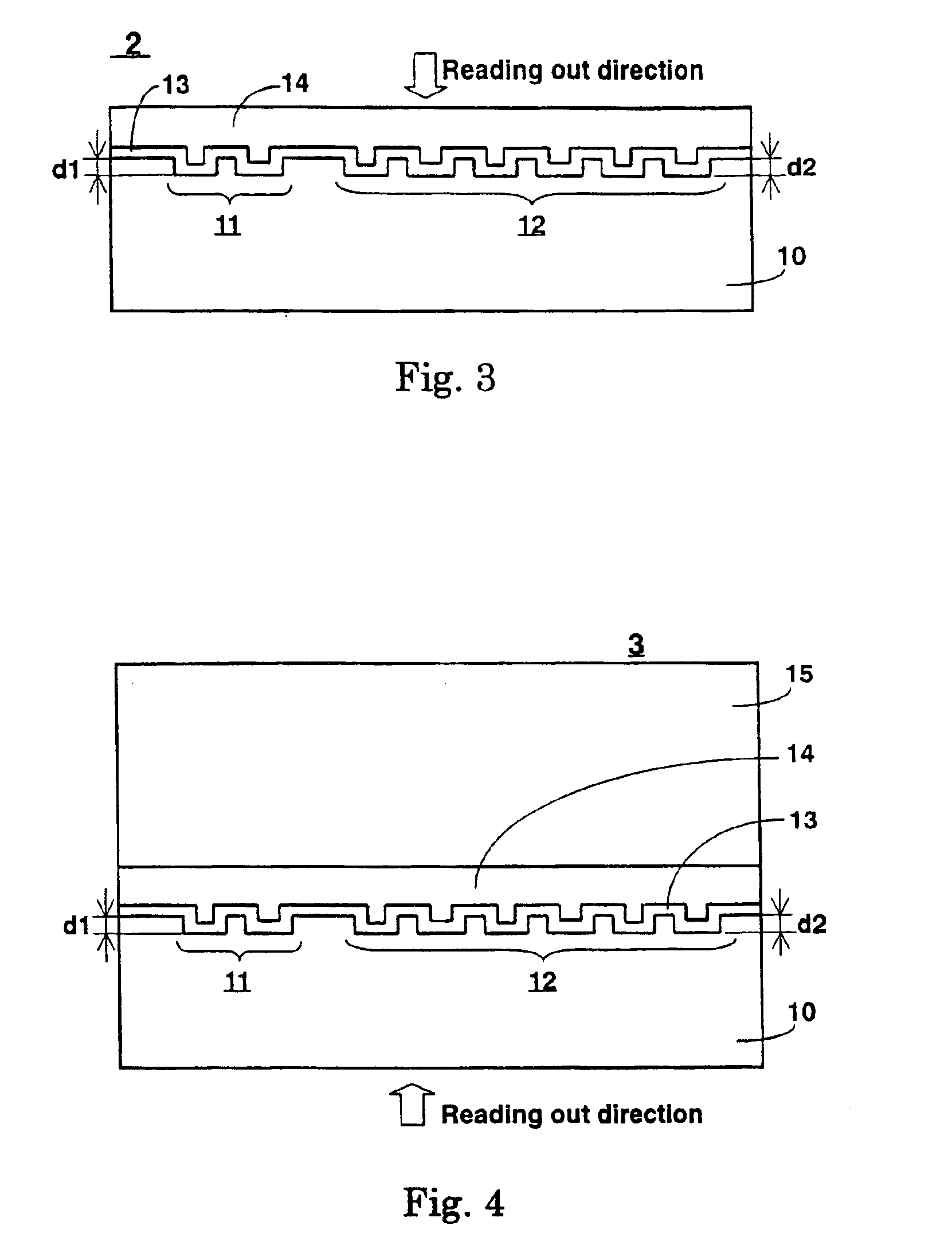
[0066]FIG. 4 is a cross sectional view of the information recording medium shown in FIG. 1 according to a first embodiment of the present invention.

[0067]In FIG. 1, an information recording medium 3 comprises a read only area 31 formed a ring shape in an inner circumference area and a recording / reproducing area 32 formed a ring shape in an area outside the read only area 31. As shown in FIG. 4, the information recording medium 3 comprises a substrate 10, a recording layer 13, a resin layer 14 and a dummy substrate 15. The resin layer 14 is adhered on the recording layer 13 with continuously covering over two areas including the read only area 31 and the recording / reproducing area 32. The substrate 13 comprises polycarbonate of which a refractive index “n” is 1.58 at a wavelength λ of 650 nm. The recording layer 13 comprises a phase chan...

second embodiment

[Second Embodiment]

[0076]Parameters of this embodiment are a same as those of the first embodiment except for (nd1 / λ)=0.18 and (nd2 / λ)=0.08. Further, the gap “G” between the read only area 31 and the recording / reproducing area 32 are specified to 20 μm. By these parameters, it is obtained that T1=0.19 and T2=0.37, and then T1 / T2=0.5 is obtained. Accordingly, the push-pull conditions of the present invention such that T1≧0.1, T2≧0.1, and 1.5≧T1 / T2≧0.5 can be satisfied. Further, reproduction jitter in the read only area 31 and the recording / reproducing area 32 are 7.1% and 6.5% respectively. Both jitter values sufficiently satisfy the standard. Furthermore, by continuously reproducing two areas, it is confirmed that a continuous reproduction can jump across the two areas without any problems.

third embodiment

[Third Embodiment]

[0077]Parameters of this embodiment are a same as those of the first embodiment except for (nd1 / λ)=0.175 and (nd2 / λ)=0.067. Further, the gap “G” between the read only area 31 and the recording / reproducing area 32 are assigned to 0.74 μm, which is the same value as P1 and P2. By these parameters, it is obtained that T1=0.20 and T2=0.33, and then T1 / T2=0.6 is obtained. Accordingly, the push-pull conditions of the present invention such that T1≧0.1, T2≧0.1, and 1.5≧T1 / T2≧0.5 can be satisfied. Further, reproduction jitter in the read only area 31 and the recording / reproducing area 32 are 7.5% and 6.3% respectively. Both jitter values sufficiently satisfy the standard. Furthermore, by continuously reproducing two areas, it is confirmed that a continuous reproduction can be performed without stopping at a boundary between two areas.


PUM

PropertyMeasurementUnit
reflectivityaaaaaaaaaa
wavelengthaaaaaaaaaa
refractive indexaaaaaaaaaa

Abstract

In an information recording medium comprising at least a substrate, a recording layer, and a resin layer, the substrate is formed with at least a pit corresponding to a read only area 31 and a groove corresponding to a recording/reproducing area 32 without overlapping with each other. A reflectivity of the recording layer is specified to be more than 10%. The recording layer and the resin layer are continuously adhered over both the read only and recording/reproducing areas 31 and 32. The information recording medium is characterized in that both push-pull signal outputs T1 and T2, which are reproduced from the read only area 31 and the recording/reproducing area 32 respectively, are more than 0.1 and satisfy an inequality 1.5≧T1/T2≧0.5.

Description

CROSS-REFERENCE APPLICATION[0001]The present application is a divisional application of U.S. application Ser. No. 10 / 435,057, filed May 12, 2003, now U.S. Pat. No. 6,744,725, which is a divisional application of U.S. application Ser. No. 09 / 825,924, filed Apr. 5, 2001, now U.S. Pat. No. 6,582,793, which claims priority from Japanese Pat. Appl. Nos. 2000-107736, filed Apr. 10, 2000 and 2000-225094, filed Jul. 26, 2000.BACKGROUND OF THE INVENTION[0002]1. Field of the Invention[0003]The present invention relates to an information recording medium utilized for an optical recording / reproducing apparatus, which reads out information recorded on the information recording medium by making the information recording medium relatively move, particularly, relates to an information recording medium comprising a read only area of enabling to read out information and a recording / reproducing area of enabling to record and reproduce information.[0004]2. Description of the Related Art[0005]Currently ...

Claims


Application Information

Patent Timeline
Patent Type & Authority Patents(United States)
IPC IPC(8): G11B7/09G11B7/007G11B7/24G11B7/0033G11B7/00G11B7/005G11B7/013G11B7/24035G11B7/24079G11B7/24085G11B7/24091G11B7/30
CPCG11B7/007G11B7/0079G11B7/0901G11B7/0938G11B7/24082G11B7/24091G11B23/40G11B7/0033Y10T428/21G11B7/24012G11B7/2585G11B20/00304G11B20/00405G11B20/00601G11B2007/24308G11B2007/2431G11B2007/24314G11B2007/24316G11B2220/211G11B7/00455
Inventor KONDO, TETSUYA
Owner JVC KENWOOD CORP A CORP OF JAPAN
Why Eureka
Try Eureka