Oil filter cap with ball valve anti-sticking device

a technology of oil filter cap and ball valve, which is applied in the direction of liquid/fluent solid measurement, level indicators by dip members, engine lubrication, etc., can solve the problems of float ball sticking, overheating of bearings, and catastrophic engine failure, and achieve the effect of preventing oil leakag

Inactive Publication Date: 2005-08-09
PRATT & WHITNEY CANADA CORP
View PDF12 Cites 10 Cited by
  • Summary
  • Abstract
  • Description
  • Claims
  • Application Information

AI Technical Summary

Benefits of technology

[0010]Therefore, the invention provides significant advantage over the prior art in automatically preventing sticking of the ball of the valve with a simple fail safe device.

Problems solved by technology

In the case of aircraft engines, the oil tank is pressurized and loss of oil during flight leads to rapid overheating of the bearings and catastrophic engine failure.
An acknowledged problem with ball valves is that the float ball often sticks to the valve seat after operation of the engine particularly when the oil tank is pressurized and the float ball is forced by pressure into engagement with the valve seat.
The blockage of the filler tube by the float ball stuck to the valve seat creates difficulty in adding oil to the tank through the filler tube and may give the false impression that the oil tank is full once oil is poured into the blocked filler tube.

Method used


Image

  • Oil filter cap with ball valve anti-sticking device
  • Oil filter cap with ball valve anti-sticking device
  • Oil filter cap with ball valve anti-sticking device

Examples


first embodiment

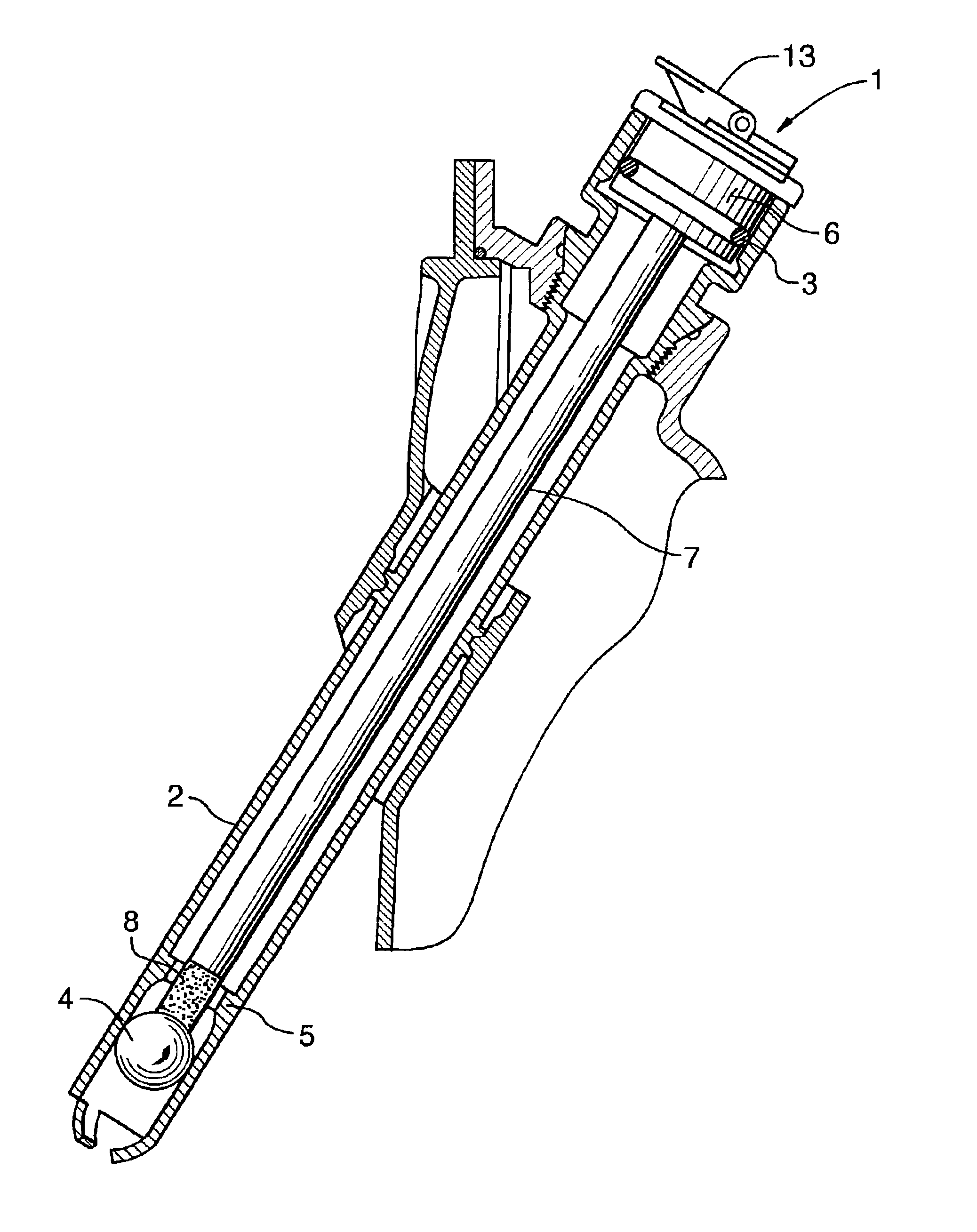
[0018]FIG. 1 illustrates a cap 1 for sealing the outer end of an oil filler tube 2. A sealable plug 6 includes an O-ring 3 that together with the latch lever 13 secures the plug and prevents oil leakage. However, during maintenance operations replacement of the oil cap may be omitted or the O-ring 3 may be damaged. In some cases, such as ship or aircraft engines, loss of fuel or oil would be dangerous or catastrophic, a back up ball valve is provided to impede any reverse flow of liquids during engine operation. The ball valve includes a float ball 4 and a valve seat 5 with a concave spherical surface to match the convex spherical surface of the float ball 4.

[0019]In order to automatically dislodge the ball 4 from the valve seat 5 and avoid sticking, the invention includes a rod 7 that extends from the plug 6 towards the inner end of the tube 2. Valve opening means are mounted to the rod 7 for dislodging the ball 4 from the valve seat 5 as follows.

[0020]In the first embodiment shown...

second embodiment

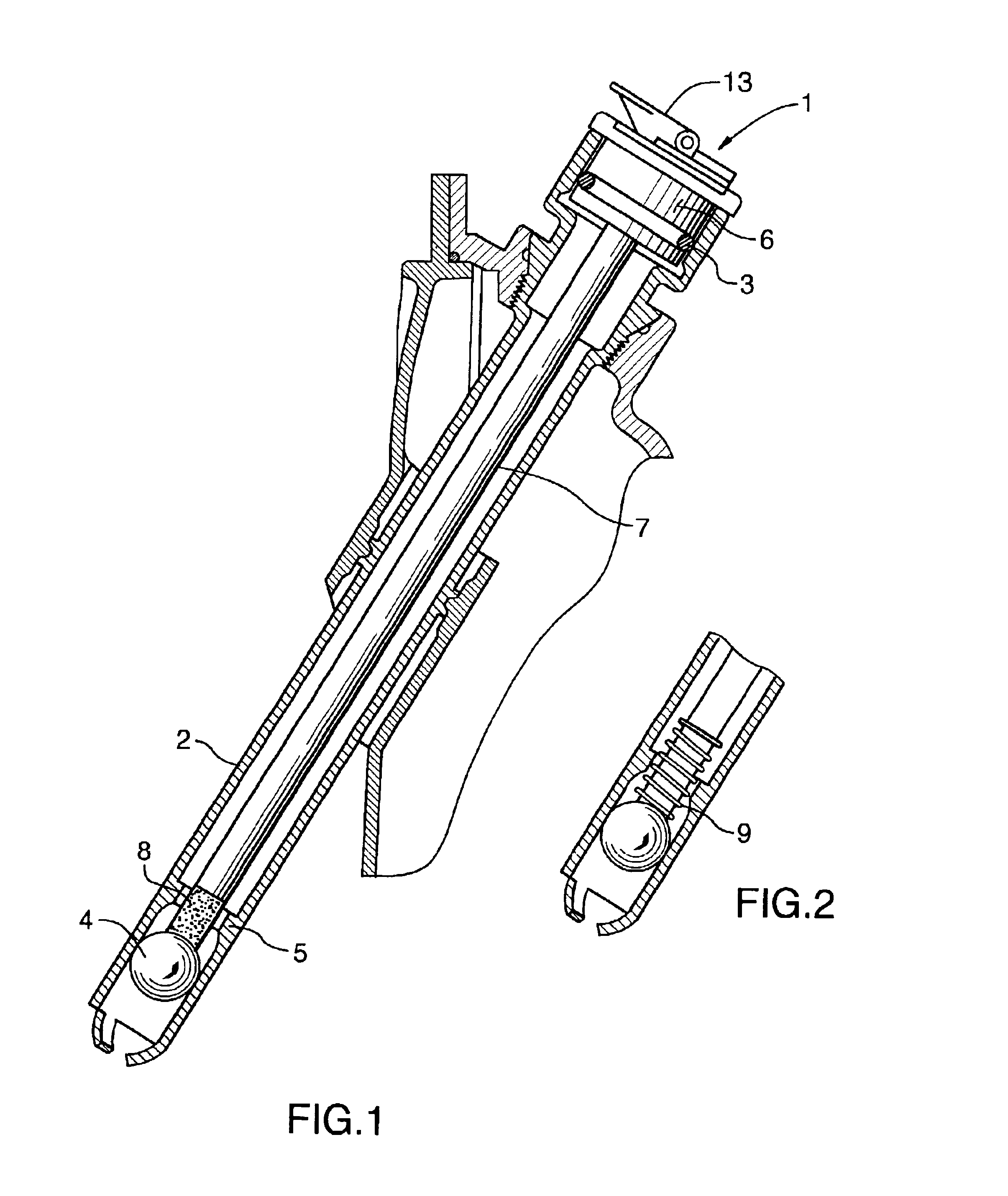
[0021]In the second embodiment shown in FIG. 2, the resilient tip comprises a coil spring 9. The resilient tip 8 made of elastomeric material and the coil spring 9 have resilience selected so they do not impede the normal operation of the ball valve. Rather the resilient tips have sufficient resilience to prevent the ball valve from sticking but can compress during normal engine operation to permit the ball valve to operate.

third embodiment

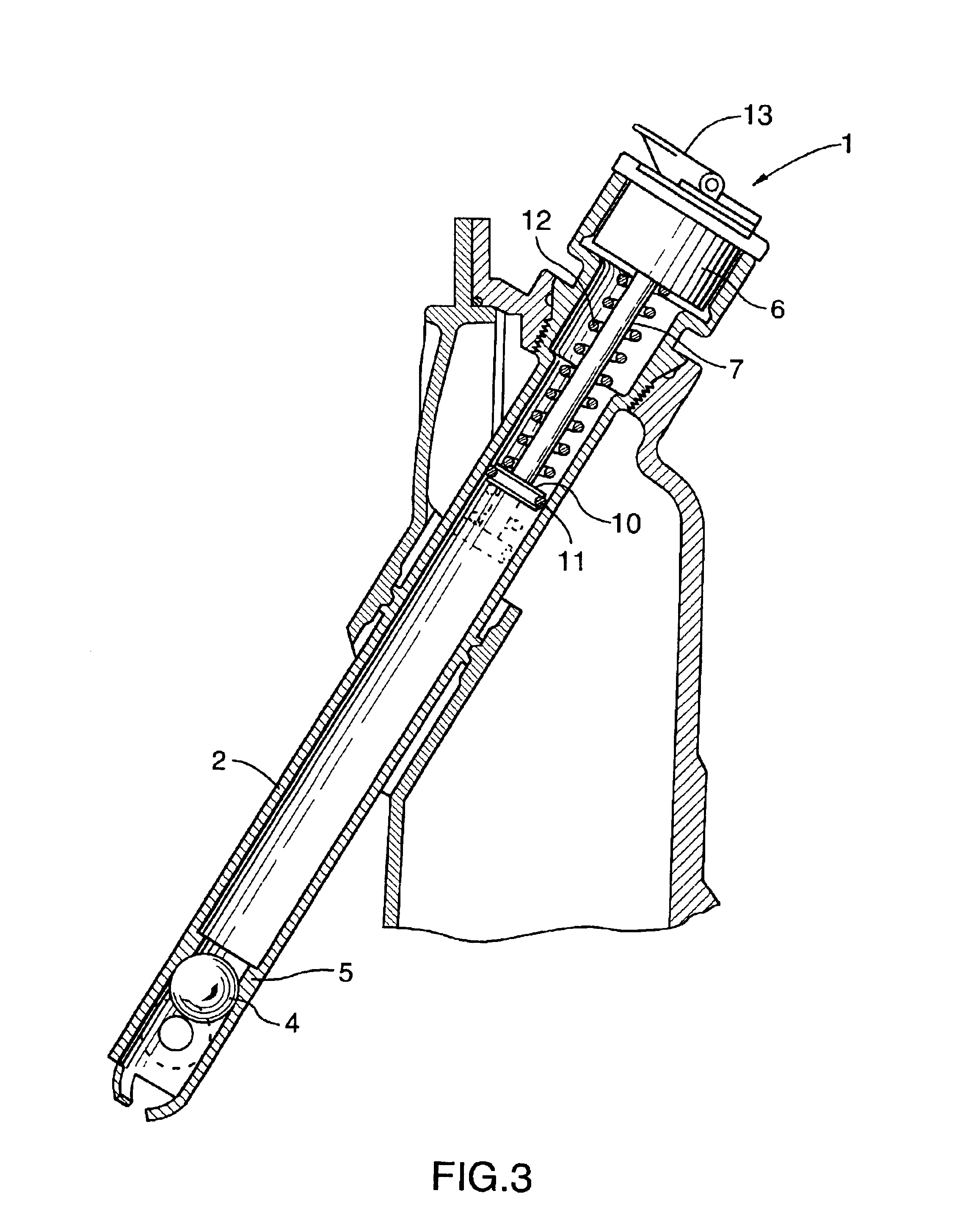
[0022]FIG. 3 shows the invention including a plug 6 where the rod 7 is slidably mounted for longitudinal motion within the tube 2. The device to disengage the ball 4 from the valve seat 5 includes a piston 10 with sliding air retaining O-ring seal 11 engaging the interior of the tube 2 when inserted. When the latch lever 13 is rotated, the spring loaded piston 10 snaps quickly to deliver a surge of pressurized air sufficient to dislodge the ball 4 from the ball seat 5. A compression spring 12 is coiled about the rod 7 confined between the piston 10 and the cap 1. The latch lever 13 is in a loaded position compressing the spring 12 when the piston 10 is disengaged from the interior of the tube 2. Therefore, when the cap 1 is replaced, the coil spring 12 is loaded as shown in dark outline in FIG. 3. The latch lever 13 when opened releases the piston 10 which moves to the position shown in dashed outline inFIG. 3 delivering a burst or surge or compressed air sufficient to dislodge the ...


PUM


Abstract

A cap for sealing an outer end of an oil filler tube of an engine where the oil filler tube has an inner end with ball valve having a float ball and mating valve seat for impeding any reverse flow of oil during engine operation. The cap includes a sealable plug mating the tube outer end; a rod extending from the plug toward the inner end of the tube; and a valve opening device mounted to the rod for dislodging the float ball from the valve seat.

Description

TECHNICAL FIELD[0001]The invention relates to an oil filler cap, for mounting in an engine oil filler tube with a back flow preventing float ball valve, where the cap includes a device to prevent sticking of the ball in the valve seat.BACKGROUND OF THE ART[0002]Engines and other machines usually include an oil filler tube to check and modify the oil volume within an oil tank. In the case of aircraft engines, the oil tank is pressurized and loss of oil during flight leads to rapid overheating of the bearings and catastrophic engine failure. In the event that the oil filler tube cap has been improperly placed or omitted altogether, oil filler tubes include a ball valve to impede oil leakage.[0003]U.S. Pat. No. 1,756,976 to Ehlers shows a float ball valve to prevent escape of oil. Another example is shown in U.S. Statutory Invention Registration No. H438 to Viksne et al. which includes a float ball valve to prevent overflow of fuel through a fuel sounding tube.[0004]An acknowledged pro...

Claims


Application Information

Patent Timeline
Patent Type & Authority Patents(United States)
IPC IPC(8): F01M11/10F01M11/12F01M11/00F01M11/06
CPCF01M11/064F01M11/12F01M2011/0041F01M2011/0491
Inventor GATES, ROGERMACFARLANE, IAN
Owner PRATT & WHITNEY CANADA CORP
Why Eureka
Try Eureka