Outboard motor steering system

a steering system and motor technology, applied in the direction of outboard propulsion units, marine propulsion, vessel construction, etc., can solve the problems of increasing the number and weight of components, affecting the steering experience, and affecting the operation efficiency of fabrication or maintenance, so as to avoid the increase in the number of components and weight, and improve the steering feel.

Inactive Publication Date: 2005-08-09
HONDA MOTOR CO LTD
View PDF4 Cites 1 Cited by
  • Summary
  • Abstract
  • Description
  • Claims
  • Application Information

AI Technical Summary

Benefits of technology

[0006]An object of the present invention is therefore to overcome the foregoing issues by providing an outboard motor steering system that is simply configured ...

Problems solved by technology

The add-on steering system constituted as a separate unit from the onboard motor has disadvantages, most notably that its structure is complicated, that it adds to the number and weight of the components, it degrades operation efficiency in fabrication or maintenance, and that it takes up space between the front of the out...

Method used


Image

  • Outboard motor steering system
  • Outboard motor steering system
  • Outboard motor steering system

Examples


first embodiment

[0029]An outboard motor steering system according to the present invention will now be explained with reference to the attached drawings.

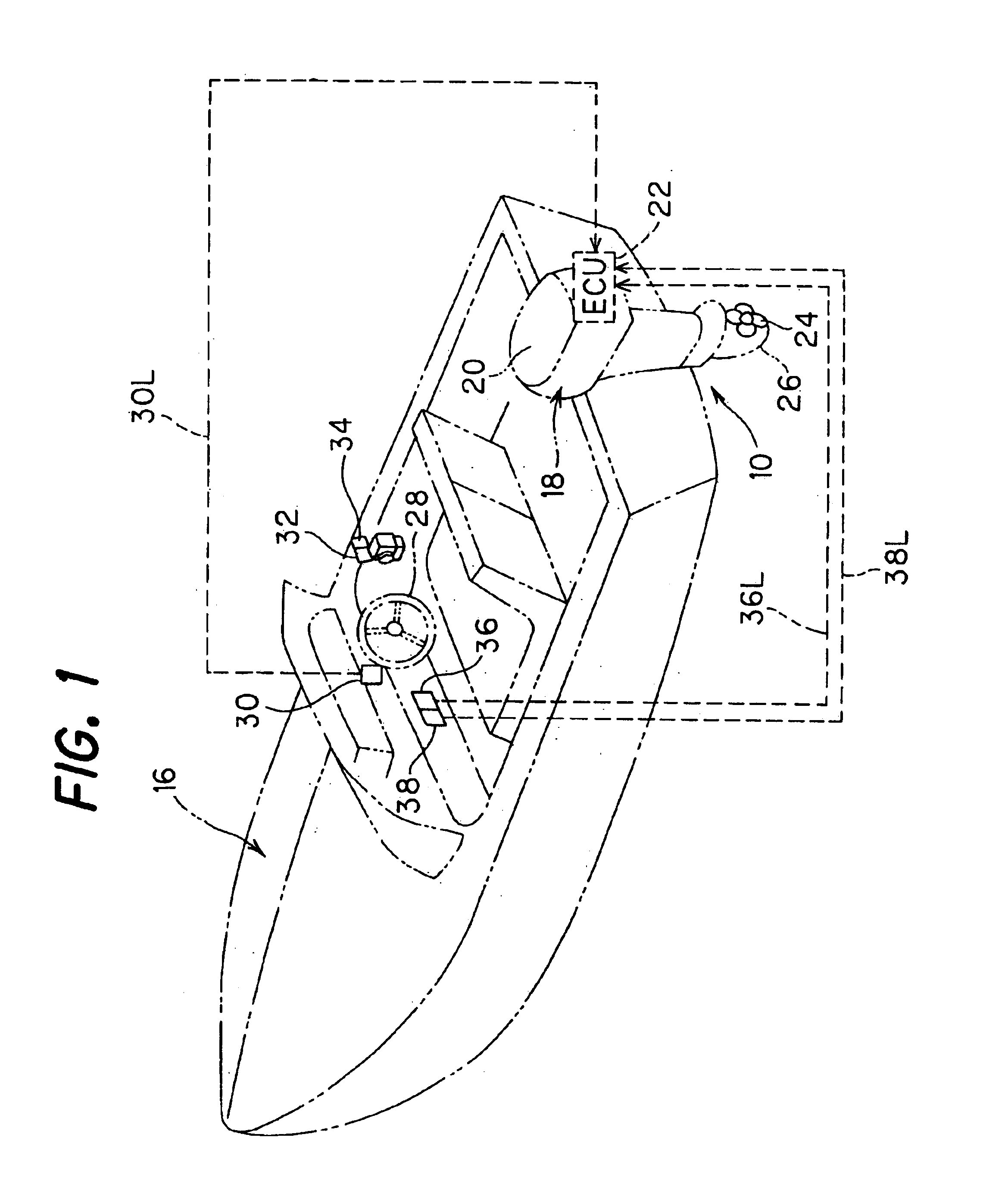
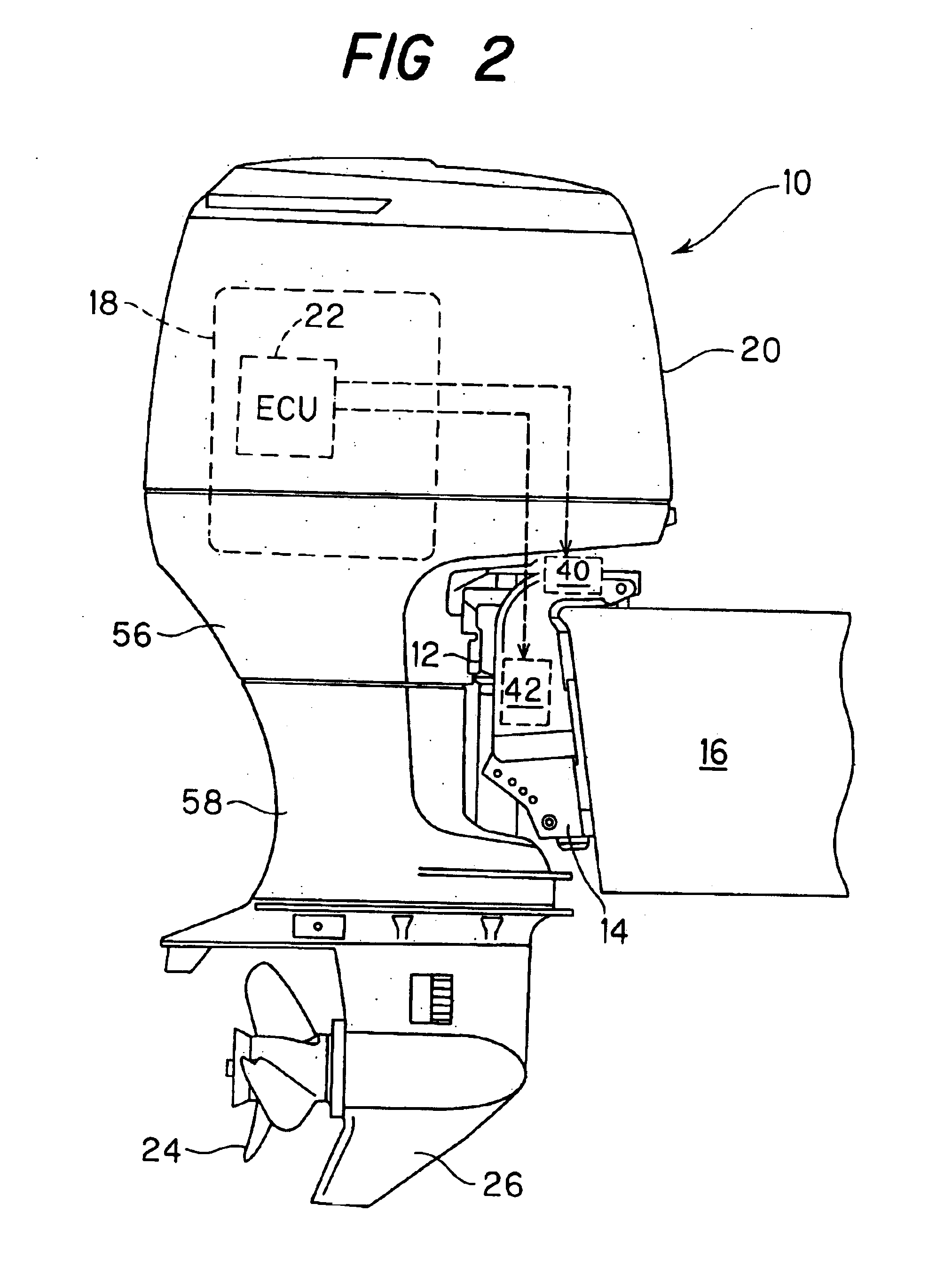
[0030]FIG. 1 is an overall schematic view of the outboard motor steering system, and FIG. 2 is an explanatory side view of a part including an outboard motor of FIG. 1.

[0031]Reference numeral 10 in FIGS. 1 and 2 designates an outboard motor built integrally of an internal combustion engine, propeller shaft, propeller and other components. As illustrated in FIG. 2, the outboard motor 10 is mounted on the stern of a boat (hull) 16 via a swivel case 12 (that houses a rotatable swivel shaft (not shown) and stern brackets 14, to be rotatable about the vertical and horizontal axes.

[0032]As shown in FIG. 2, the outboard motor 10 is equipped with an internal combustion engine 18 at its upper portion. The engine 18 is a spark-ignition, in-line four-cylinder gasoline engine with a displacement of 2,200 cc. The engine 18, located inside the outboard motor 10,...

second embodiment

[0070]An outboard motor steering system according to the invention will now be explained with reference to FIG. 6 and FIG. 7.

[0071]FIG. 6 and FIG. 7 are view, similar to FIG. 2 and FIG. 3, but showing the outboard motor steering system according to the second embodiment of the invention. The same reference numerals in these figures and on indicate the same elements used in the first embodiment.

[0072]Explaining this with focus on the differences from the first embodiment, in the second embodiment, instead of the double-acting cylinder 40, a pair of single-acting cylinders (hydraulic actuators) 100 are housed inside the swivel case 12 to rotate the swivel shaft 50.

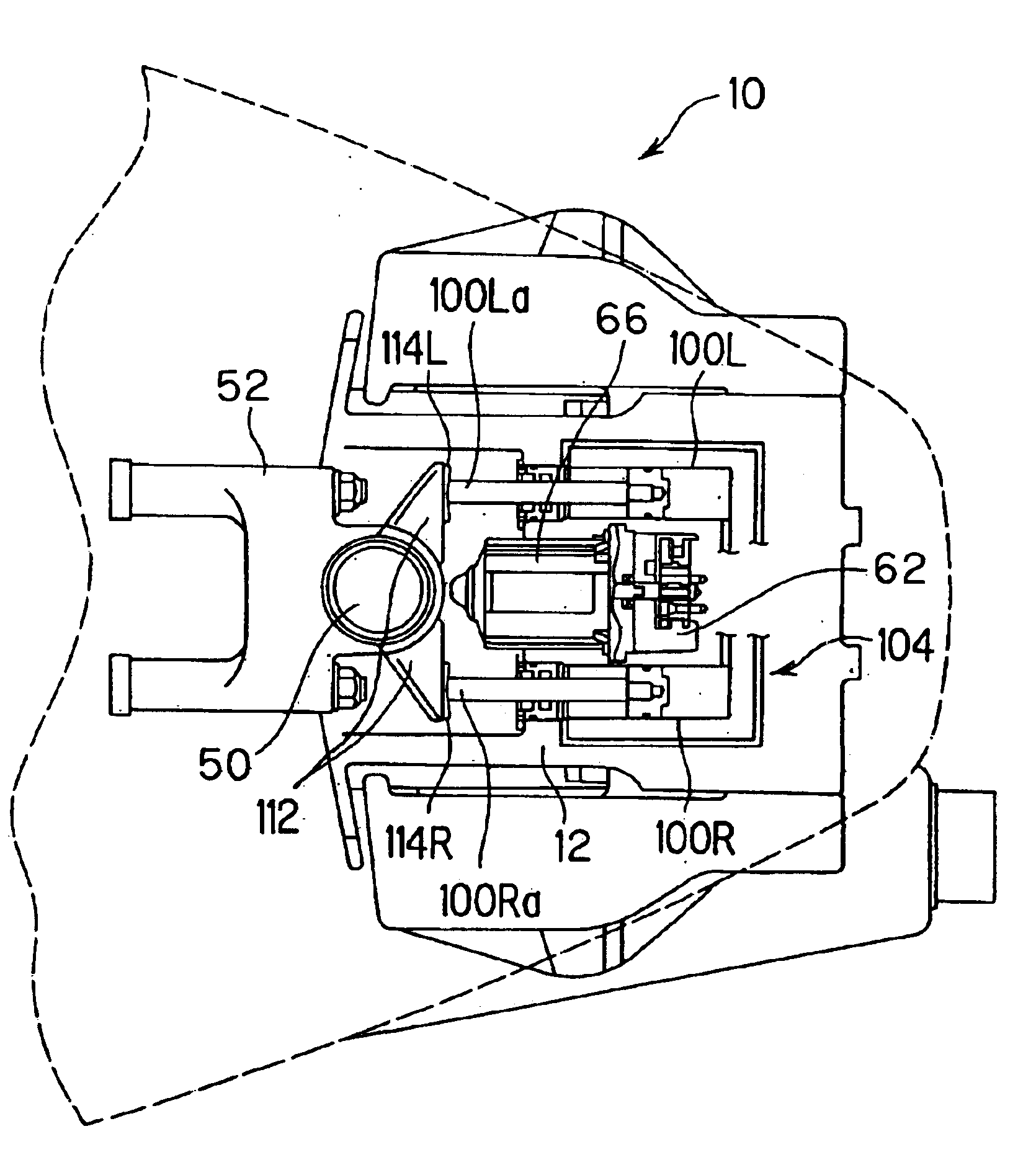
[0073]FIG. 8 is a cross-sectional view taken along VIII—VIII line of FIG. 7.

[0074]As shown in FIGS. 7 and 8, within the interior space of the swivel case 12, there are housed and fixed the aforesaid two single-acting cylinders 100 (the right one is referred to as the “first single-acting cylinder 100R” and the left one “seco...

third embodiment

[0094]An outboard motor steering system according to the invention will now be explained with reference to FIG. 10 and FIG. 11.

[0095]FIG. 10 and FIG. 11 are views, similar to FIG. 2 and FIG. 3, but showing the outboard motor steering system according to the third embodiment of the invention. The same reference numerals in these figures and on indicate the same elements used in the first embodiment.

[0096]Explaining this with focus on the differences from the foregoing embodiments, in the third embodiment, instead of the hydraulic cylinders used in the systems according to the foregoing embodiments, a rotary vane motor (hydraulic actuator) 200 is housed inside the swivel case 12 to rotate the swivel shaft 50.

[0097]FIG. 12 is a cross-sectional view taken along XII—XII line of FIG. 11.

[0098]As shown in FIGS. 11 and 12, the swivel case 12 is enlarged and in the interior space formed there, the rotary vane motor (hereinafter referred to as the “vane motor”) 200 is housed and fixed at the ...


PUM


Abstract

An outboard motor steering system for an outboard motor mounted on a stern of a boat and having an internal combustion engine at its upper portion and a propeller with a rudder at its lower portion that is powered by the engine to propel and steer the boat, having a swivel shaft connected to the propeller to turn the propeller relative to the boat and housed in a swivel case, a hydraulic actuator such as a double-acting cylinder connected to the swivel shaft to rotate the swivel shaft, a hydraulic pressure supplier connected to the hydraulic actuator to supply hydraulic pressure, and a controller that controls supply of the hydraulic pressure to the hydraulic actuator in response to a steering signal inputted by an operator such that the outboard motor is steered relative to the boat. In the system, the hydraulic actuator and the hydraulic pressure supplier are housed in the swivel case. The system is thus simply configured to avoid increase in number of components and weight, and does not cause a problem regarding space utilization and operation efficiency, while improving steering feel.

Description

BACKGROUND OF THE INVENTION[0001]1. Field of the Invention[0002]This invention relates to an outboard motor steering system.[0003]2. Description of the Related Art[0004]In outboard motor steering systems, an add-on mechanism constituted as a separate unit from the outboard motor and used to power-assist the turning of the tiller handle is known. For example, as taught in Japanese Laid-Open Patent Application Sho 62 (1987)-125996, this mechanism typically includes an actuator such as a steering hydraulic (oil) cylinder whose driving end (piston rod head) is connected to the tiller handle through an arm or the like, and a hydraulic pump that is connected to the steering mechanism to operate in response to the angle of steering. The hydraulic cylinder is connected to the hydraulic pump by a hydraulic hose or pipe attached to the boat (hull) to be supplied with pressurized oil from the pump such that the steering of the tiller handle by human power to turn the rudder is power-assisted.[...

Claims


Application Information

Patent Timeline
IPC IPC(8): B63H20/00B63H20/12
CPCB63H20/12
Inventor MIZUGUCHI, HIROSHITAKADA, HIDEAKIWATABE, HIROSHIOTOBE, TAIICHIMASUBUCHI, YOSHINORI
Owner HONDA MOTOR CO LTD
Why Eureka
Try Eureka