
Seat back structure with lumbar support for vehicle

a technology of lumbar support and seat back, which is applied in the direction of vehicle components, vehicle arrangements, chairs, etc., can solve the problems of increasing the number of components, increasing the cost, and insufficient headrests alone as a countermeasure against neck injuries, so as to avoid the increase in both the number of components and the weigh

Inactive Publication Date: 2012-08-30
DELTA KOGYO CO LTD
View PDF12 Cites 4 Cited by
  • Summary
  • Abstract
  • Description
  • Claims
  • Application Information

AI Technical Summary

Benefits of technology

[0018]The present invention was devised in order to eliminate the aforementioned problems, an object thereof being to provide a structure of a seat back with lumbar support for a vehicle which avoids increase in both the number of components and weight, by devising a mechanism of a lumbar supporting function so as to serve also as a mechanism providing a countermeasure against neck injury.
[0026]By devising the lumbar support device having a lumbar support function so as to also include a function of providing a neck injury countermeasure in this way, the number of components is reduced, costs are also lowered, and increase in weight can be avoided.

Problems solved by technology

However, a headrest alone is not sufficient as a countermeasure against neck injuries.
Therefore, in order to provide both a lumbar supporting function and a countermeasure against neck injury, it is necessary to provide both a composition having a lumbar supporting function and a composition having a countermeasure against neck injury, and therefore the number of components increases, costs also rise, and the weight also increases.

Method used


Image

  • Seat back structure with lumbar support for vehicle
  • Seat back structure with lumbar support for vehicle
  • Seat back structure with lumbar support for vehicle

Examples


Embodiment Construction

[0037]Hereinbelow, a mode of implementing the present invention is described in detail with reference to the drawings. Parts which have the same composition and action as the prior art are labeled with the same reference numbers and detailed description thereof is omitted here.

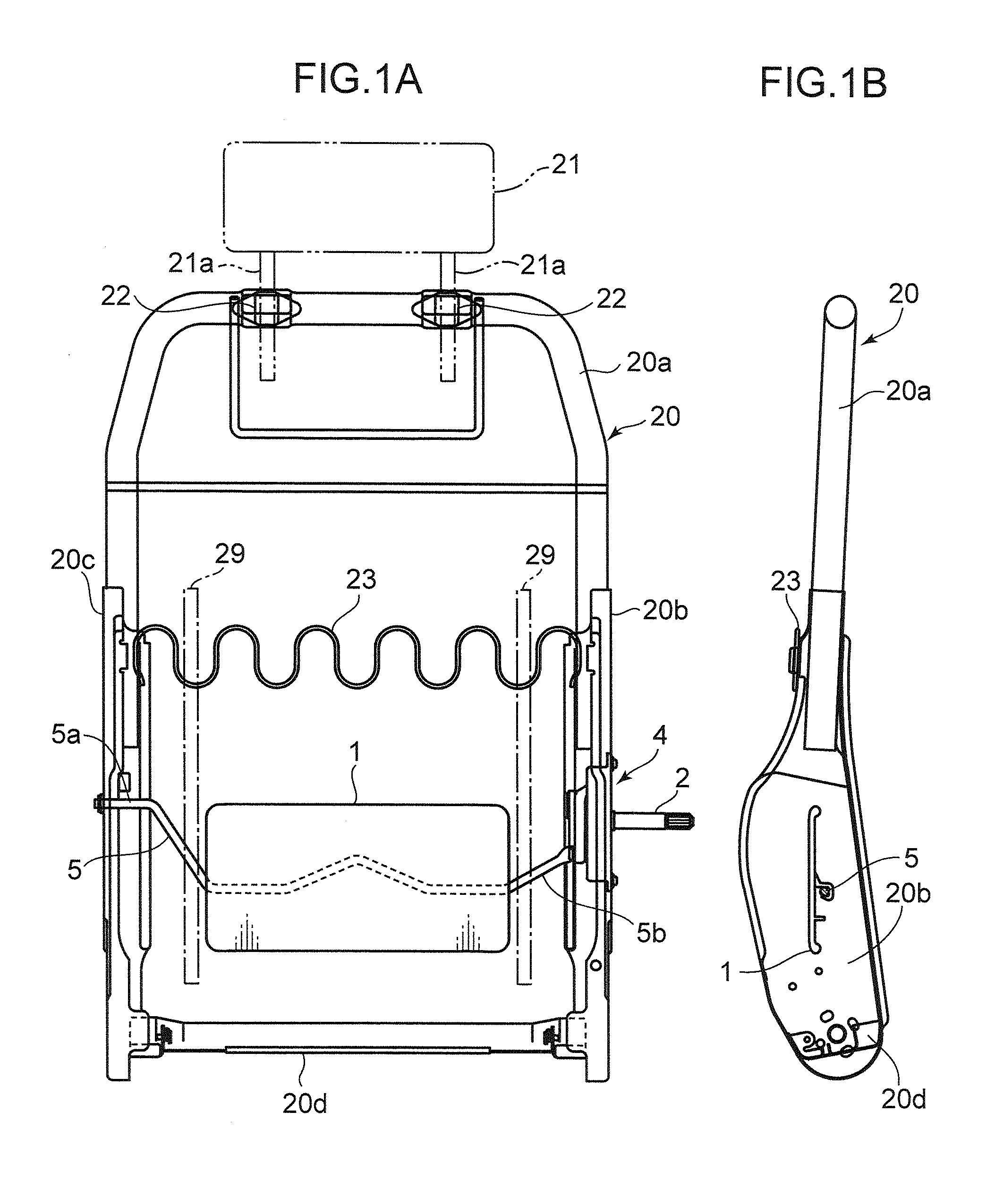
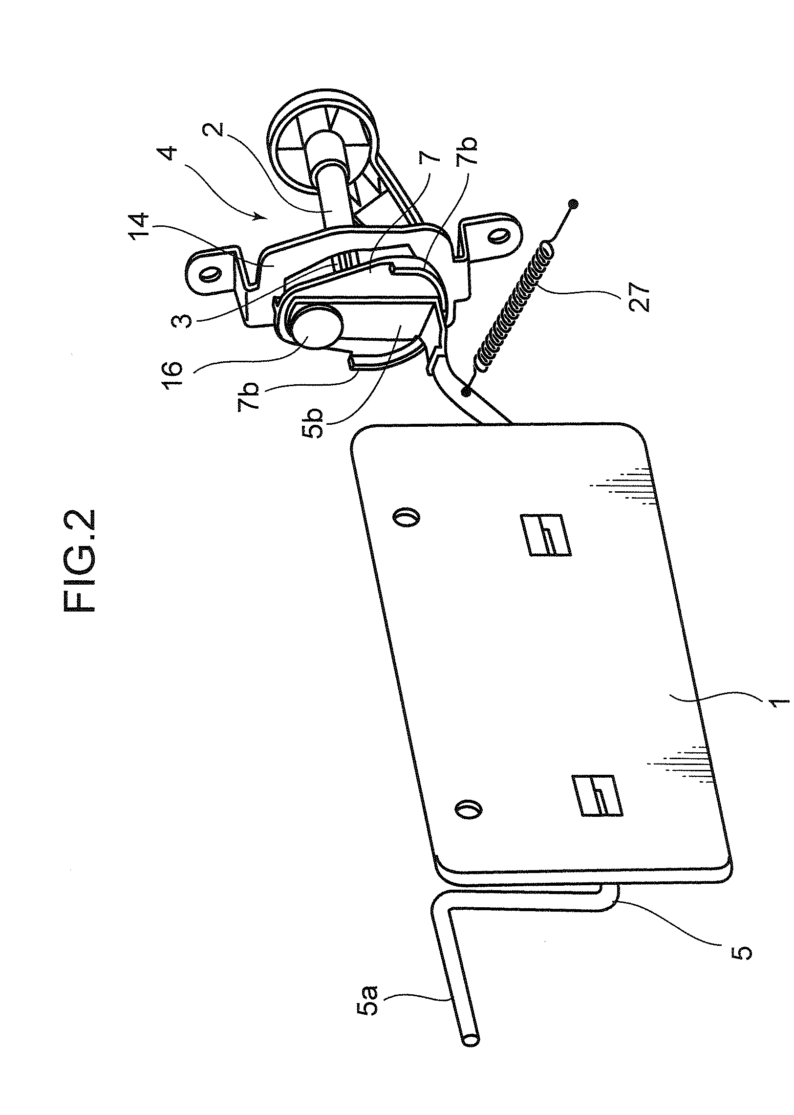
[0038]FIG. 1 shows an internal frame structure of a seat back for a vehicle seat, in which FIG. 1A is a front face diagram and FIG. 1B is a side face cross-sectional diagram. FIG. 2 is a perspective diagram of a lumbar support plate, a torsion bar and a clutch mechanism.

[0039]The back frame 20 of the seat back is constituted by an inverted U-shaped upper frame 20a, left and right-hand side frames 20b, 20c which are respectively fixed to the left and right-hand portions of the upper frame 20a, and a lower frame 20d which couples the lower portions of the left and right-hand side frames 20b and 20c.

[0040]A pole guide 22 which supports poles 21a of a headrest 21 is fixed to the upper frame 20a.

[0041]A horizonta...


PUM


Abstract

A lumbar support plate which is supported movably in a front / rear direction in a back frame that supports a headrest, and a biasing member which supports the lumbar support plate, are provided. A clutch mechanism which enables an output member to rotate by a rotating operation of a handle shaft, and an adjustment member which is capable of adjusting the front / rear position of the lumbar support plate in relation with an output member of the clutch mechanism are also provided. Also provided is a linking release mechanism which temporarily releases linkage with the clutch mechanism and permits rearward movement of the lumbar support plate, when a load equal to or greater than a prescribed value is applied to the lumbar support plate.

Description

BACKGROUND OF THE INVENTION[0001]1. Field of the Invention[0002]The present invention relates to a structure of a seat back with lumbar support for a vehicle.[0003]2. Description of the Related Art[0004]In a vehicle, and in particular an automobile, a headrest is provided in the upper part of a seat back as a countermeasure against neck injury (whiplash) in a vehicle occupant in the event of a rear collision. However, a headrest alone is not sufficient as a countermeasure against neck injuries.[0005]Therefore, it has been proposed to provide a coupling member which extends rearwards only when a load equal to or exceeding a prescribed value is applied, in the coupling portion of a seat back frame with an S spring (a cushion spring which is bent in a continuous plurality of S shapes) (see, for example, Japanese Patent Application Laid-open No. H7-291005).[0006]When the weight of a vehicle occupant acts on an S spring as a reaction to a rear impact, the coupling member extends rearward...

Claims


Application Information

Patent Timeline
Patent Type & Authority Applications(United States)
IPC IPC(8): B60N2/66
CPCB60N2/66B60N2/42727
Inventor OKAMOTO, MASAFUMIOKIMOTO, RYOTA
Owner DELTA KOGYO CO LTD
Learn More