Electronic device

Inactive Publication Date: 2009-03-26
SANYO ELECTRIC CO LTD
3 Cites 8 Cited by

AI-Extracted Technical Summary

Problems solved by technology

In most of electronic devices of this type, the speaker is positioned on an outer side of a liquid crystal display part in a front view, but positioning the speaker on the outer side of the liquid crystal display part causes a problem of an increas...

Method used

[0031]As shown in FIG. 1 to FIG. 3, the speakers 28 are provided on the rear side of the liquid crystal display part 20, inside the casing front portion 12A so as to partly protrude downward from the liquid crystal display part 20, and the sound guide ducts 24 extend linearly from the front face side of the speakers 28 toward the front face side of the casing front portion 12A. Thus, the sound guide ducts 24 are not bent. Therefore, even high-frequency sound generated from the speakers 28 can be outputted to the external part of the casing 12 without any sound quality deterioration. Further, since the speakers 28 do not have to be disposed on the front face of the casing 12 which is on the outer side of the liquid crystal display part 20, the electronic device 10 can be made compact, resulting in reduction in weight of the electronic device 10. As a result, the electronic device 10 can be easily disposed even in a limited space such as, for example, the interior of an automobile.
[0032]The sound guide ducts 24 can be formed by using existing constituent members basically necessary for the electronic device 10 es...

Benefits of technology

[0012]According to the invention of claim 1, the speaker is provided on the rear side of the display part, inside the casing so as to partly protrude from the display part, and the sound guide part guiding the sound generated from the speaker to the external part of the casing extends linearly from the front face side of the speaker, and thus the sound guide part is not bent. Therefore, even high-frequency sound generated from the speaker can be outputted to the external part of the casing without any deterioration in sound quality. Further, since the speaker is provided on the rear side of the display part, inside the casing so as to partly protrude from the display part, the speaker does not have to be disposed on the front face of the casing which is on the outer side of the display part, as in conventional electronic devices. This can make the electronic device compact, resulting in weight reduction of the electronic device. As a result, the electronic device can be easily disposed in a limited space such as, for example, the interior of an automobile.
[0013]According to the invention of claim 2, since the sound guide part also has the display part fixing function of fixing the display part, it is possible to form a sound guide channel by using an existing constituent member basically required for the electronic devi...

Abstract

To provide an electronic device whose manufacturing cost and weight can be reduced and whose sound quality can be prevented from deteriorating.
Speakers 28 are provided on a rear side of a liquid crystal display part 20, inside a casing 12 so as to partly protrude downward from the liquid crystal display part 20, and sound guide ducts 24 linearly extend from a front face side of the speakers 28, and thus the sound guide ducts 24 are not bent. Therefore, even high-frequency sound generated from the speakers 28 can be outputted to an external part of the casing 12 without any sound quality deterioration. Further, the speakers 28 do not have to be disposed on a front face of the casing 12 which is on an outer side of the liquid crystal display part 20, and therefore, an electronic device 10 can be made compact, which can reduce weight and manufacturing cost of the electronic device 10.

Application Domain

Television system detailsDigital data processing details +5

Technology Topic

LoudspeakerLiquid-crystal display +5

Image

  • Electronic device
  • Electronic device
  • Electronic device

Examples

  • Experimental program(1)

Example

EXPLANATION OF CODES
[0019] 10 electronic device [0020] 12 casing [0021] 20 liquid crystal display part (display part) [0022] 24 sound guide duct (sound guide part) [0023] 28 speaker
BEST MODE FOR CARRYING OUT THE INVENTION
[0024]Next, an electronic device according to an embodiment of the present invention will be described with reference to the drawings. It should be noted that the electronic device of the present invention is widely applicable to, for example, a liquid crystal television set, a car navigation system, and so on.
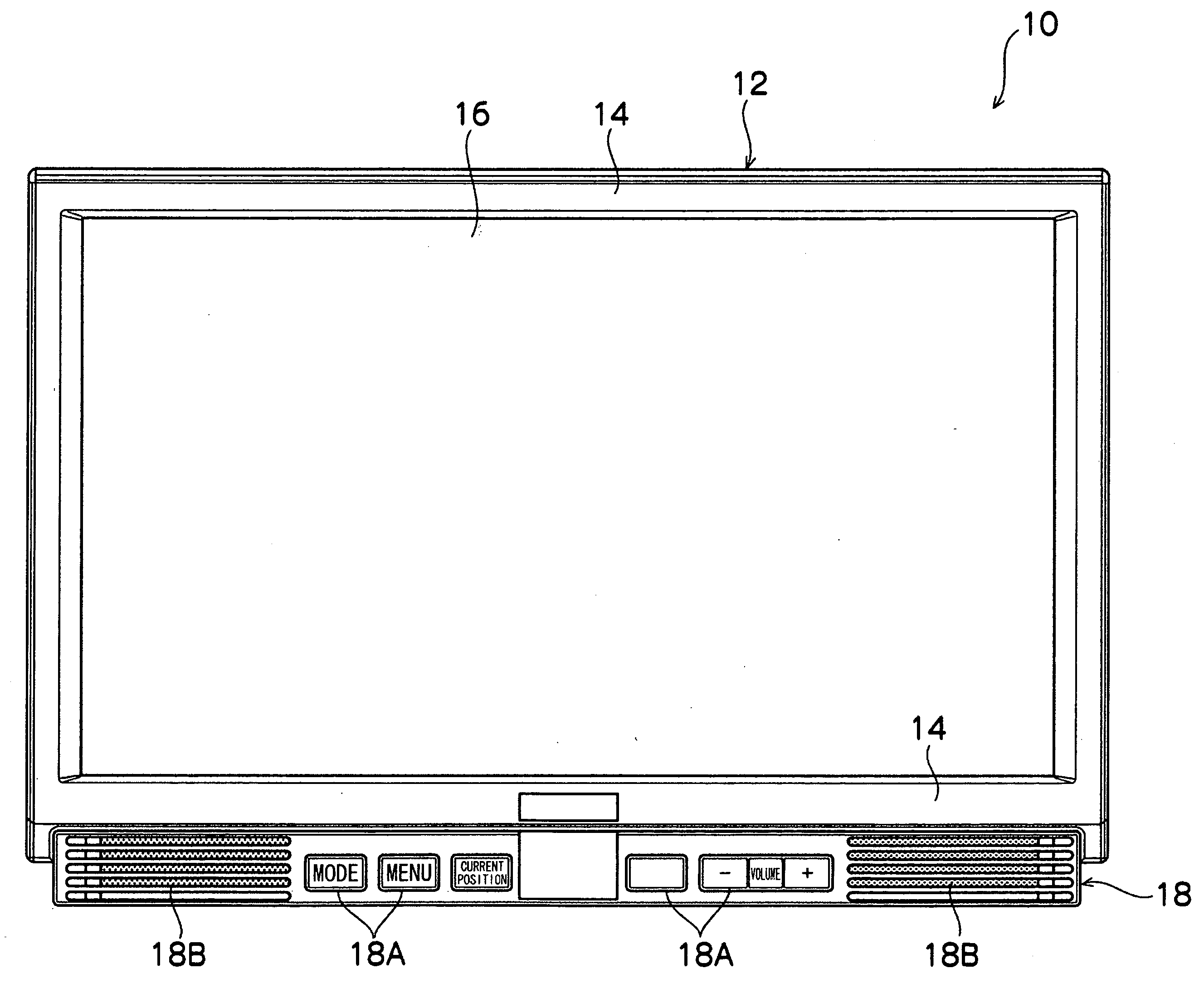
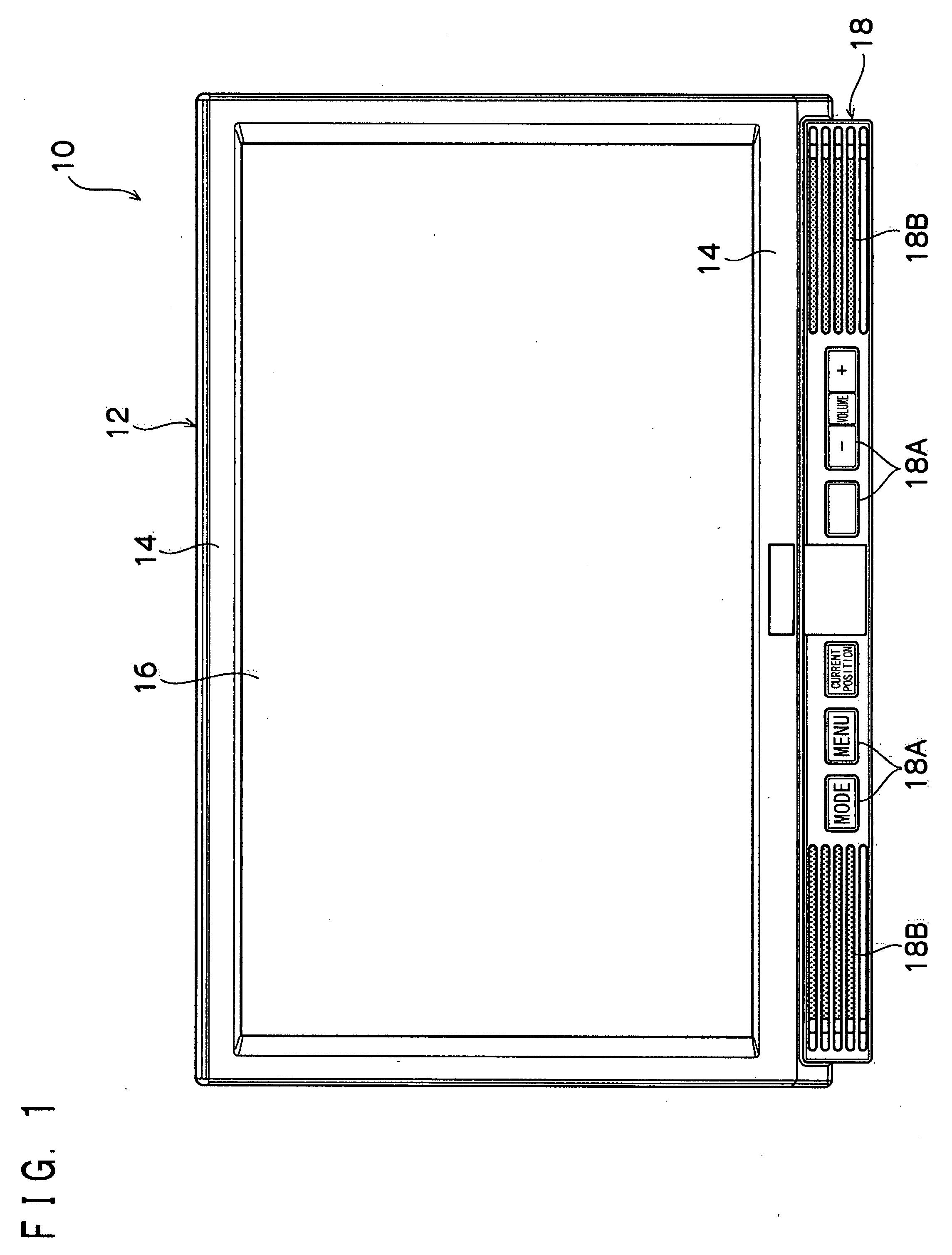
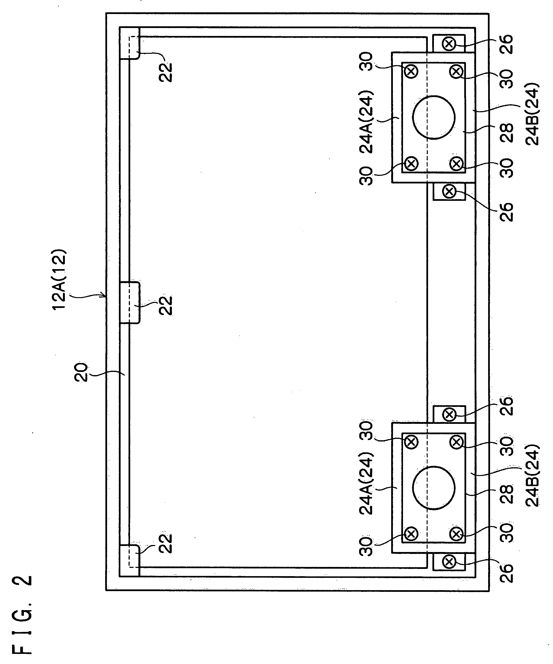
[0025]As shown in FIG. 1 to FIG. 3, an electronic device 10 includes a box-shaped casing 12 as an outer frame. The casing 12 is composed of a casing front portion 12A positioned on a forward (front face) side and a casing rear portion 12B positioned on a backward (rear face) side which are combined with each other. Support parts 14 are formed in front of (on a front face side of) the casing front portion 12A, and a touch panel part 16 is disposed behind (on rear face side of) the support parts 14. Further, in front of (on a front face side of) the casing 12, an operation part 18 is provided under the touch panel part 16. In the operation part 18, input buttons 18A and so on necessary for the operation are disposed. Further, in left and right portions of the operation part 18, slit parts 18B forming entrances of later-described sound guide ducts (sound guide parts) 24 are provided respectively.
[0026]Further, inside the casing front portion 12A, a liquid crystal display part (display part) 20 displaying predetermined information is disposed behind (on a rear face side of) the touch panel part 16. The liquid crystal display part 20 together with the touch panel part 16 is positioned and fixed inside the casing front portion 12A by claw portions 22 formed on the casing front portion 12A, upper sound guide duct parts 24A constituting the later-described sound guide ducts 24, and the aforesaid support parts 14.
[0027]Further, as shown in FIG. 2, inside the casing front portion 12A, the sound guide ducts (sound guide parts) 24 guiding sound generated from later-described speakers 28 to the front face of the casing front portion 12A are attached to left and right lower portions of the liquid crystal display part 20 by screws 26, respectively. Each of the sound guide ducts 24 is attached to the casing front portion 12A and is formed as a space closed by the upper sound guide duct part 24A positioning and fixing the liquid crystal display part 20 and a lower sound guide part 24B attached to the casing front portion 12A. Therefore, sound generated from the later-described speakers 28 is outputted from the slit parts 18B without leaking to an external part of the casing 12. Further, the upper sound guide duct parts 24A and the lower sound guide duct parts 24B are made of a material not transmitting light, such as, for example, black plastic resin.
[0028]Further, as shown in FIG. 2, each of the speakers 28 is attached by screws 30 to a rear end portion of the upper sound guide duct part 24A and a rear end portion of the lower sound guide duct part 24B. In more detail, each of the sound guide ducts 24 extends linearly from the front face side of the speaker 28 toward the front face side of the casing front portion 12A. Incidentally, a front end portion of each of the upper sound guide duct parts 24A and a front end portion of each of the lower sound guide duct parts 24B are connected to the slit part 18B. Further, the speakers 28 are provided on the rear side of the liquid crystal display part 20, inside the casing front portion 12A so as to partly protrude downward from the liquid crystal display part 20.
[0029]As described above, in the electronic device 10 of this embodiment, the sound guide ducts 24 also have a display part fixing function of fixing the liquid crystal display part 20 and also has a speaker fixing function of fixing the speakers 28.
[0030]Next, the operation of the electronic device 10 of this embodiment will be described.
[0031]As shown in FIG. 1 to FIG. 3, the speakers 28 are provided on the rear side of the liquid crystal display part 20, inside the casing front portion 12A so as to partly protrude downward from the liquid crystal display part 20, and the sound guide ducts 24 extend linearly from the front face side of the speakers 28 toward the front face side of the casing front portion 12A. Thus, the sound guide ducts 24 are not bent. Therefore, even high-frequency sound generated from the speakers 28 can be outputted to the external part of the casing 12 without any sound quality deterioration. Further, since the speakers 28 do not have to be disposed on the front face of the casing 12 which is on the outer side of the liquid crystal display part 20, the electronic device 10 can be made compact, resulting in reduction in weight of the electronic device 10. As a result, the electronic device 10 can be easily disposed even in a limited space such as, for example, the interior of an automobile.
[0032]The sound guide ducts 24 can be formed by using existing constituent members basically necessary for the electronic device 10 especially because the sound guide ducts 24 also have the display part fixing function of fixing the liquid crystal display part 20. This can prevent an increase in the number of assembly processes and weight of the electronic device 10, as contrast to a case where the sound guide ducts are formed by using independent members different from fixing parts fixing the liquid crystal display part 20. Further, since by the output of sound from the speakers 28, not only the casing 12 can be resonated but also the liquid crystal display part 20 can be resonated via the sound guide ducts 24, it is possible to improve quality of sound outputted from the speakers 28.
[0033]Likewise, since the sound guide ducts 24 also have the speaker fixing function of fixing the speakers 28, the sound guide ducts 24 can be formed by using existing constituent members basically necessary for the electronic device 10. This can prevent an increase in the number of assembly processes and weight of the electronic device 10, as contrast to a case where the sound guide parts are formed by using different independent members fixing the speakers 28.
[0034]Further, since the sound guide ducts 24 are made of a material not transmitting light (in this embodiment, black plastic resin), light from the liquid crystal display part 20 and the operation part 18 can be prevented from transmitting through the sound guide ducts 24 and leaking to the external part of the casing 12 via the slit parts 18B, even in the structure where especially the sound guide ducts 24 also have the display part fixing function of fixing the liquid crystal display part 20.

PUM

no PUM

Description & Claims & Application Information

We can also present the details of the Description, Claims and Application information to help users get a comprehensive understanding of the technical details of the patent, such as background art, summary of invention, brief description of drawings, description of embodiments, and other original content. On the other hand, users can also determine the specific scope of protection of the technology through the list of claims; as well as understand the changes in the life cycle of the technology with the presentation of the patent timeline. Login to view more.

Similar technology patents

Compositions and methods for reducing food intake and controlling weight

InactiveUS20070082107A1reduce caloric intakereduce weight
Owner:MCNEIL NUTRITIONALS

Cooling fan

ActiveUS20100068060A1excellent in strength balancereduce weight
Owner:MITSUBA CORP

New megapixels wide-angle lens

ActiveCN101587232Areduce weightlow cost
Owner:NINGBO SUNNY AUTOMOTIVE OPTECH

Classification and recommendation of technical efficacy words

  • reduce weight

Electrically driven brake booster

InactiveUS20020158510A1reduce weightsimple construction
Owner:BOSCH AUTOMOTIVE SYST CORP

Display device

ActiveUS20140043546A1reduce weightreduce detection sensitivity
Owner:SEMICON ENERGY LAB CO LTD

Curved Automatic-Darkening Filter

InactiveUS20140168546A1reduce weightlow weight
Owner:3M INNOVATIVE PROPERTIES CO

Thermal Solution for Prismatic Lithium Ion Battery Pack

ActiveUS20130115506A1reduce weight
Owner:NEOGRAF SOLUTIONS LLC
Why Eureka
Try Eureka