

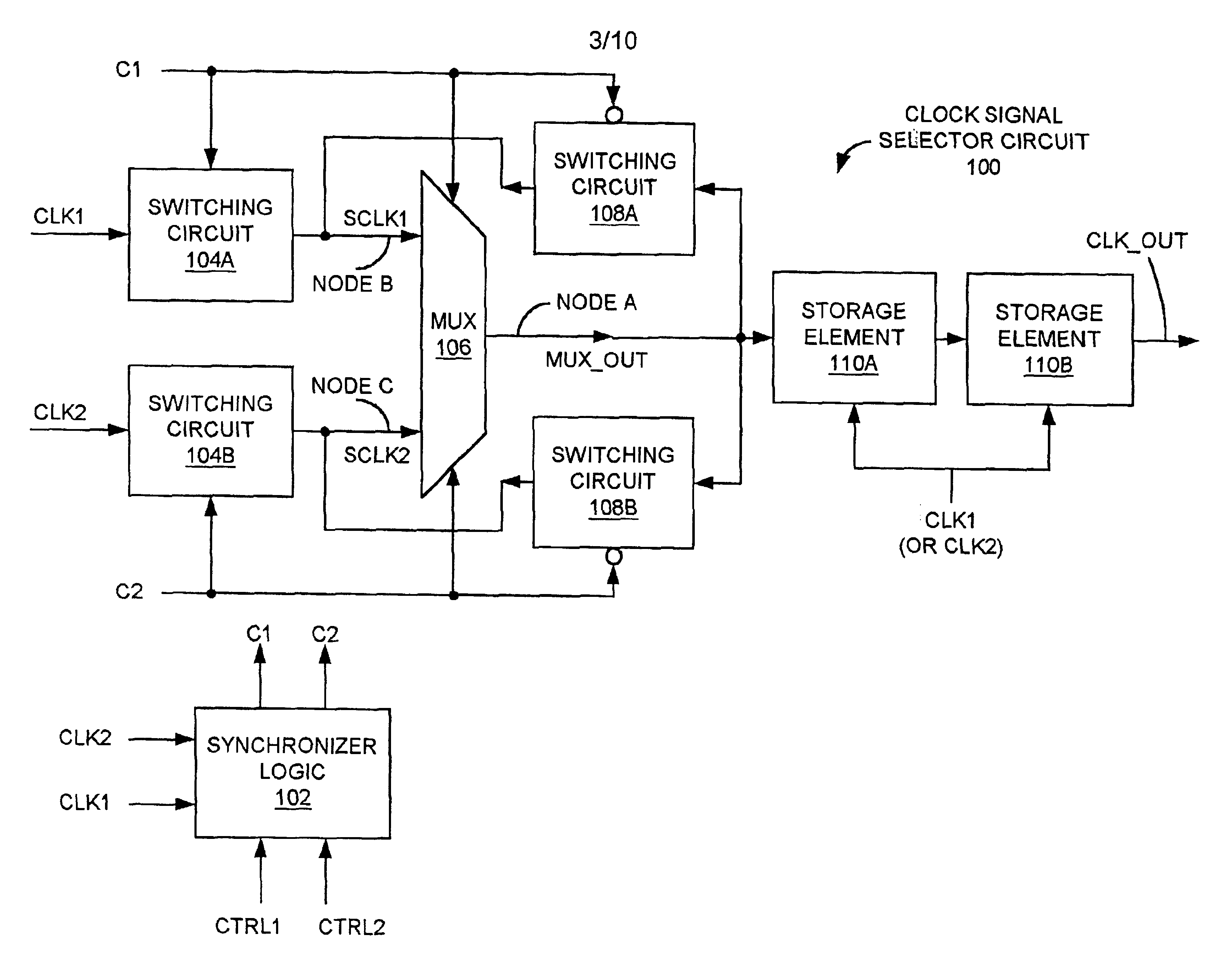
Clock signal selector circuit with reduced probability of erroneous output due to metastability
a selector circuit and clock signal technology, applied in the field of electronic circuits, can solve the problems of logic error within the logic circuitry, narrow pulses or “glitches” of the clock signal multiplexer or selector, and general unpredictable operation of the flip-flop, so as to reduce the probability of error
- Summary
- Abstract
- Description
- Claims
- Application Information
AI Technical Summary
Benefits of technology
Problems solved by technology
Method used
Image

Examples
Embodiment Construction
[0031]In the following discussion, numerous specific details are set forth to provide a thorough understanding of the present invention. However, those skilled in the art will appreciate that the present invention may be practiced without such specific details. In other instances, well-known elements have been illustrated in schematic or block diagram form in order not to obscure the present invention in unnecessary detail. Additionally, for the most part, details concerning network communications, electromagnetic signaling techniques, and the like, have been omitted inasmuch as such details are not considered necessary to obtain a complete understanding of the present invention, and are considered to be within the understanding of persons of ordinary skill in the relevant art.
[0032]It is further noted that, unless indicated otherwise, all functions described herein may be performed in either hardware or software, or some combination thereof. In a preferred embodiment, however, the ...
PUM
 Abstract
Description
Claims
Application Information