Read/write head for a magnetic tape device having grooves for reducing tape floating

Inactive Publication Date: 2005-08-09
FUJITSU LTD
View PDF13 Cites 14 Cited by
  • Summary
  • Abstract
  • Description
  • Claims
  • Application Information

AI Technical Summary

Benefits of technology

[0003]The read/write head for a magnetic tape device in accordance with the inven

Problems solved by technology

This has been difficult to accomplish, particularly in magnetic tape de

Method used


Image

  • Read/write head for a magnetic tape device having grooves for reducing tape floating
  • Read/write head for a magnetic tape device having grooves for reducing tape floating
  • Read/write head for a magnetic tape device having grooves for reducing tape floating

Examples


Example

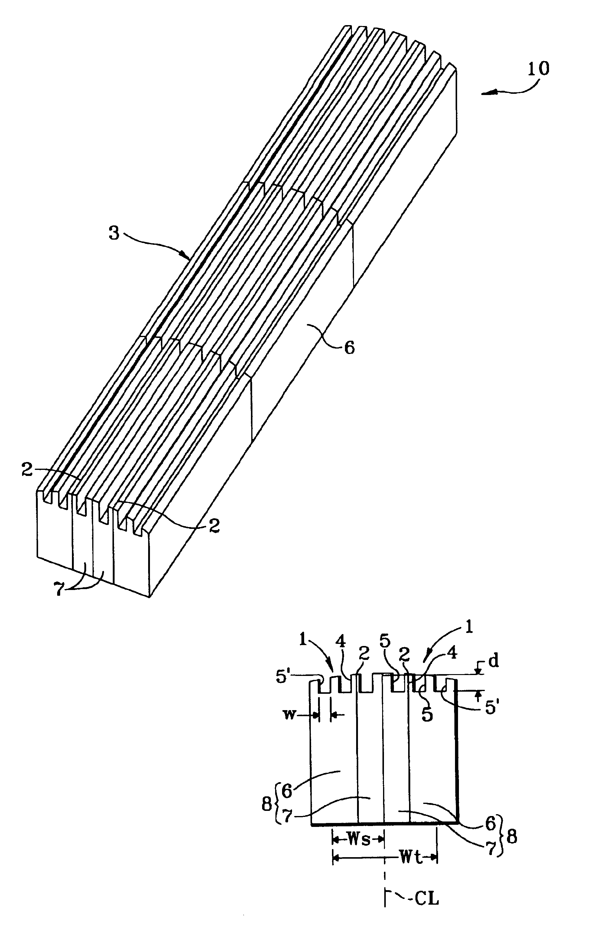
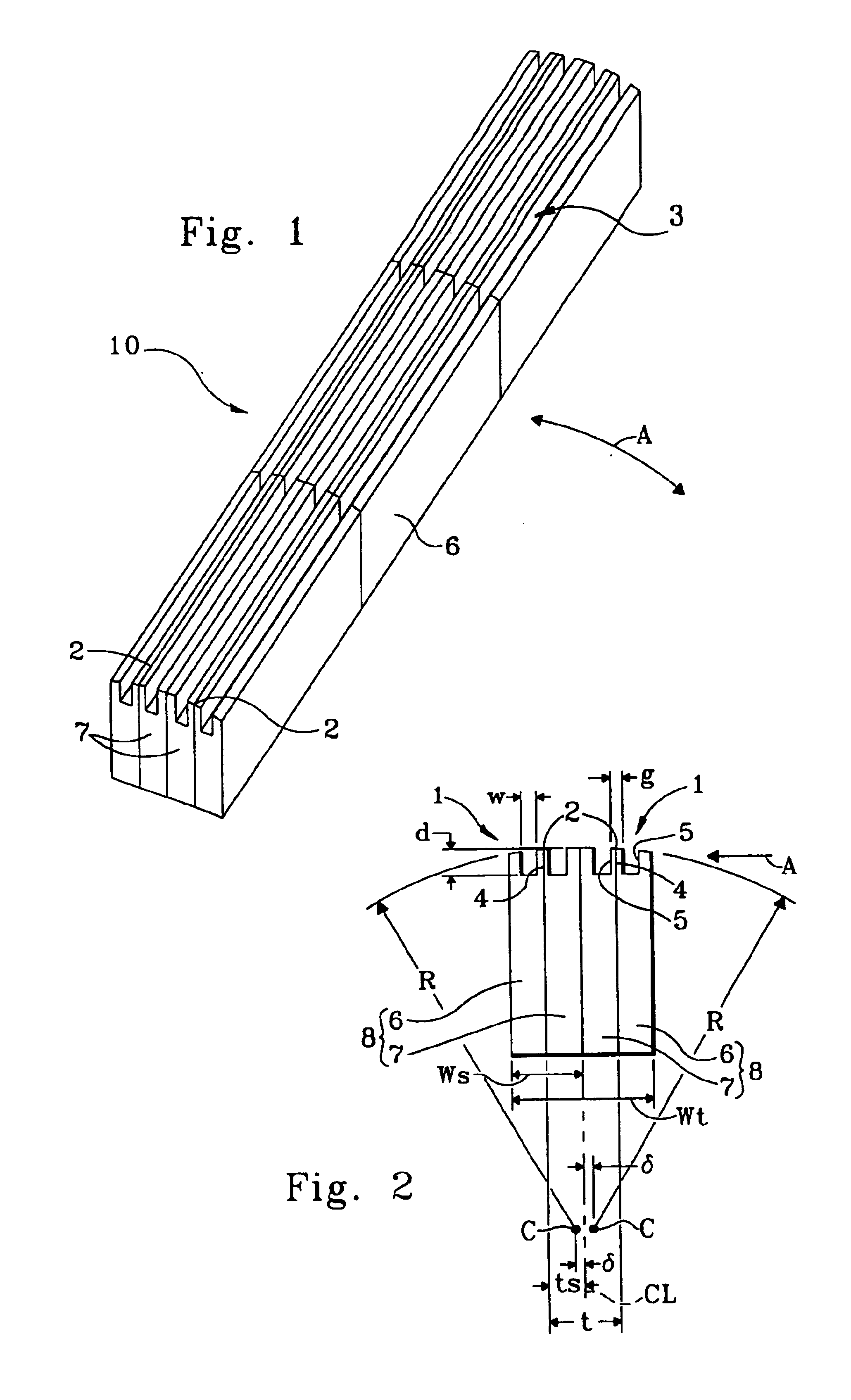
[0009]Broadly stated, the present invention is directed to a read / write head of a magnetic tape, and includes a first elongated chip assembly which is fixedly adhered to a second elongated chip assembly, a tape running surface formed in the longitudinal direction of the chip assemblies, and a read / write gap line for supporting a read / write element extending longitudinally along the tape running surface on each of the two chip assemblies. The head also includes at least one groove formed on both sides of the read / write gap line on each of the chip assemblies. The grooves extend substantially parallel to the read / write gap line.

[0010]In accordance with another aspect of the invention, a read / write head for a magnetic tape includes an elongated chip assembly and a tape running surface formed in the longitudinal direction of the chip assembly. A pair of substantially spaced parallel read / write gap lines for supporting read / write elements extend longitudinally along the tape running surf...


PUM


Abstract

A read/write head for a magnetic tape includes an elongated chip assembly and a tape running surface formed in the longitudinal direction of the chip assembly. A pair of substantially spaced parallel read/write gap lines for supporting read/write elements extend longitudinally along the tape running surface of the chip assembly. Also, at least one groove is formed on the tape running surface on both sides of each of the read/write gap lines and extends substantially parallel to the read/write gap lines.

Description

BACKGROUND[0001]The present invention generally relates to magnetic tape devices, and more particularly to a read / write head of a magnetic tape device which is configured and adapted to reduce the amount of tape floating that occurs at high tape speeds.[0002]In general, conventional read / write heads used in typical magnetic tape devices are constructed such that the magnetic tape travels over a tape running surface of the heads. Reading and writing operations are conducted on the tape using read / write elements which are arranged along the tape running surface. To conduct the reading and writing operations with a suitable level of efficiency, the amount of tape floating, i.e., the distance between the tape running surface of the head and the recording surface of the tape, needs to be reduced as much as possible while the magnetic tape is traveling over the running surface. This has been difficult to accomplish, particularly in magnetic tape devices that generate high magnetic tape sp...

Claims


Application Information

Patent Timeline
IPC IPC(8): G11B5/10G11B5/584G11B5/265G11B5/29G11B5/187
CPCG11B5/10G11B5/584G11B5/2651G11B5/295
Inventor AOKI, KENJI
Owner FUJITSU LTD
Why Eureka
Try Eureka