Swirling aggregation air flotation degreasing column

A technology of swirling air flotation and coalescence air flotation, which is applied in the direction of grease/oily substance/suspended matter removal device, flotation water/sewage treatment, water/sewage multi-stage treatment, etc., which can solve the low efficiency of oil removal and suspended matter removal , can not maintain the best gas-liquid ratio, uneven release of bubbles and other problems, to achieve the effect of shortening the floating and sinking time, shortening the residence time, and strengthening the effect of coarse graining

Pending Publication Date: 2017-09-15
ZHEJIANG JINLONG AUTOMATIC CONTROL EQUIP
View PDF8 Cites 8 Cited by
  • Summary
  • Abstract
  • Description
  • Claims
  • Application Information

AI Technical Summary

Problems solved by technology

Its disadvantages are high investment, large floor area, easy existence of air in the swirling air-dissolving tank, uneven release of bubbles, inability to maintain the best gas-liquid ratio, and low efficiency of removing oil and suspended matter

Method used


Image

  • Swirling aggregation air flotation degreasing column
  • Swirling aggregation air flotation degreasing column
  • Swirling aggregation air flotation degreasing column

Examples


Embodiment

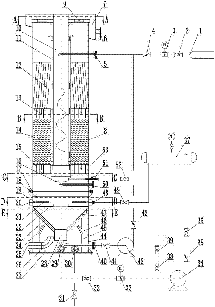
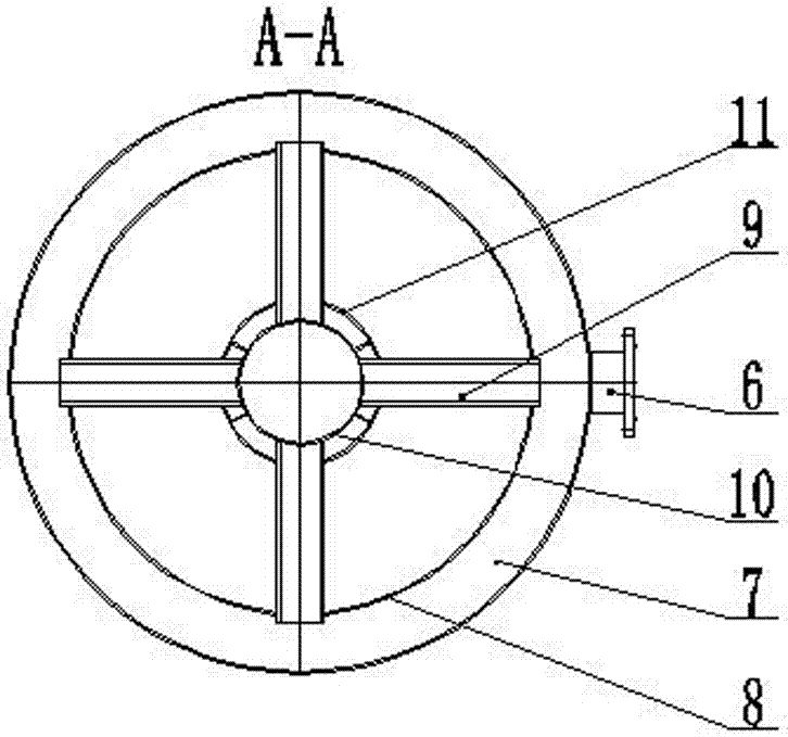
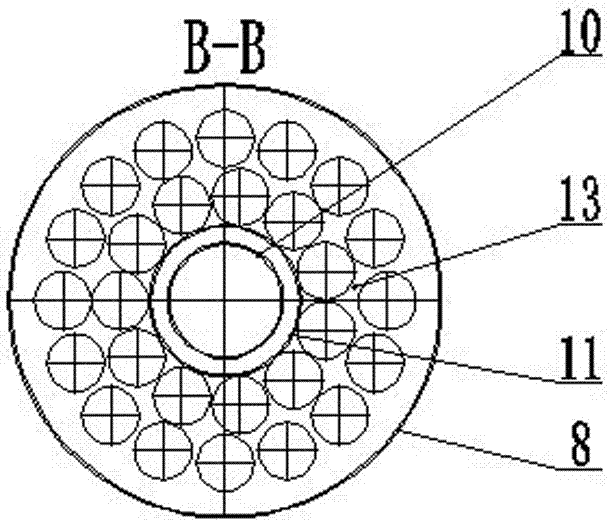
[0031] Such as Figure 1 to Figure 6 A swirl coalescing air flotation degreasing column shown includes a lower air flotation column 44, an upper air flotation column 8, and a swirl dissolved air tank 37, and the upper air flotation column 8 is connected with the lower air flotation column 44 An O-ring 17 is arranged between them, and a bottom plate 27 is arranged at the bottom of the lower air flotation column 44 .

[0032] The upper air flotation column 44 is provided with a swirl air flotation column outer cylinder 11, the swirl air flotation column outer cylinder 11 is connected with the swirl dissolved air tank 37, and the bottom of the swirl air flotation column outer cylinder 11 is provided with Lower head 16, the bottom of the lower head 16 of the swirl air flotation column outer cylinder 11 is provided with a central swirl air flotation column blowdown pipe 50 extending to the outside of the upper air flotation column 8, the swirl air flotation column outer cylinder 11...


PUM


Abstract

The invention relates to a swirling aggregation air flotation degreasing column, which comprises a lower air flotation column, an upper air flotation column and a swirling dissolved air tank, wherein a swirling air flotation oil collection tank, a floating residue discharging port, a swirling air flotation column outer cylinder, a center swirling air flotation column, a water distribution pore plate, a support pipe, an egg tray shaped disk sheet aggregation filler, a support pipe and an aggregation inclination plate filler are arranged in the upper air flotation column, the swirling air flotation column outer cylinder is connected to the swirling dissolved air tank, a baffle, a dissolved air release device, a separation plate, a sludge collection cone cylinder, a water purification area, a water outlet, a dissolved air water outlet and a venting port are arranged in the lower air flotation column, the dissolved air release device is communicated to the swirling dissolved air tank, the bottom portion of the sludge collection cone cylinder is provided with a precipitation cylinder, the bottom portion of the precipitation cylinder is communicated to the water inlet of the center swirling air flotation column, the precipitation cylinder is communicated to the water purification area, the water purification area is communicated to the lower air flotation column, and the dissolved air water outlet is connected to the swirling dissolved air tank. According to the present invention, the swirling aggregation air flotation degreasing column has advantages of simple structure, high degreasing efficiency, high suspended solid removal efficiency, fine and uniformly-dispersed air bubbles, and the like.

Description

technical field [0001] The invention relates to an air flotation device used in the field of oily sewage treatment in oil fields, in particular to a swirling flow coalescence air flotation deoiling column. Background technique [0002] A large amount of oily sewage is produced in oil field development, refining and production, with oil content ranging from tens of mg / L to several thousand mg / L. Some sewage contains polymers, which is difficult to treat. If these oily sewage are not treated, they will be discharged into the natural environment. It will inevitably cause oil pollution to natural water bodies and soil. Dissolved air flotation is one of the commonly used oily sewage treatment equipment, mainly composed of air flotation tank, air compressor, water pump, air storage tank, cyclone dissolved air tank, dissolved air water releaser, etc. Its disadvantages are high investment, large floor space, easy existence of air in the swirling air-dissolving tank, uneven release ...

Claims


Application Information

Patent Timeline
Patent Type & Authority Applications(China)
IPC IPC(8): C02F9/02
CPCC02F9/00C02F1/40C02F1/38C02F1/24C02F2001/007C02F2103/10
Inventor 余金海余正伦史佳池爱文
Owner ZHEJIANG JINLONG AUTOMATIC CONTROL EQUIP
Why Eureka
Try Eureka