Apparatus for impedance imaging coupled with another modality

a technology of impedance imaging and apparatus, applied in the field of medical imaging techniques, can solve the problems of inconvenient x-ray imaging, difficult to compare the results exactly, and inability to perform impedance imaging, and achieve the effect of enhancing the contrast of a desired featur

a technology of impedance imaging and apparatus, applied in the field of medical imaging techniques, can solve the problems of inconvenient x-ray imaging, difficult to compare the results exactly, and inability to perform impedance imaging, and achieve the effect of enhancing the contrast of a desired featur

US6928315B1Inactive Publication Date: 2005-08-09TRANSSCAN MEDICAL

Image

  • Apparatus for impedance imaging coupled with another modality
  • Apparatus for impedance imaging coupled with another modality
  • Apparatus for impedance imaging coupled with another modality

Examples


Embodiment Construction

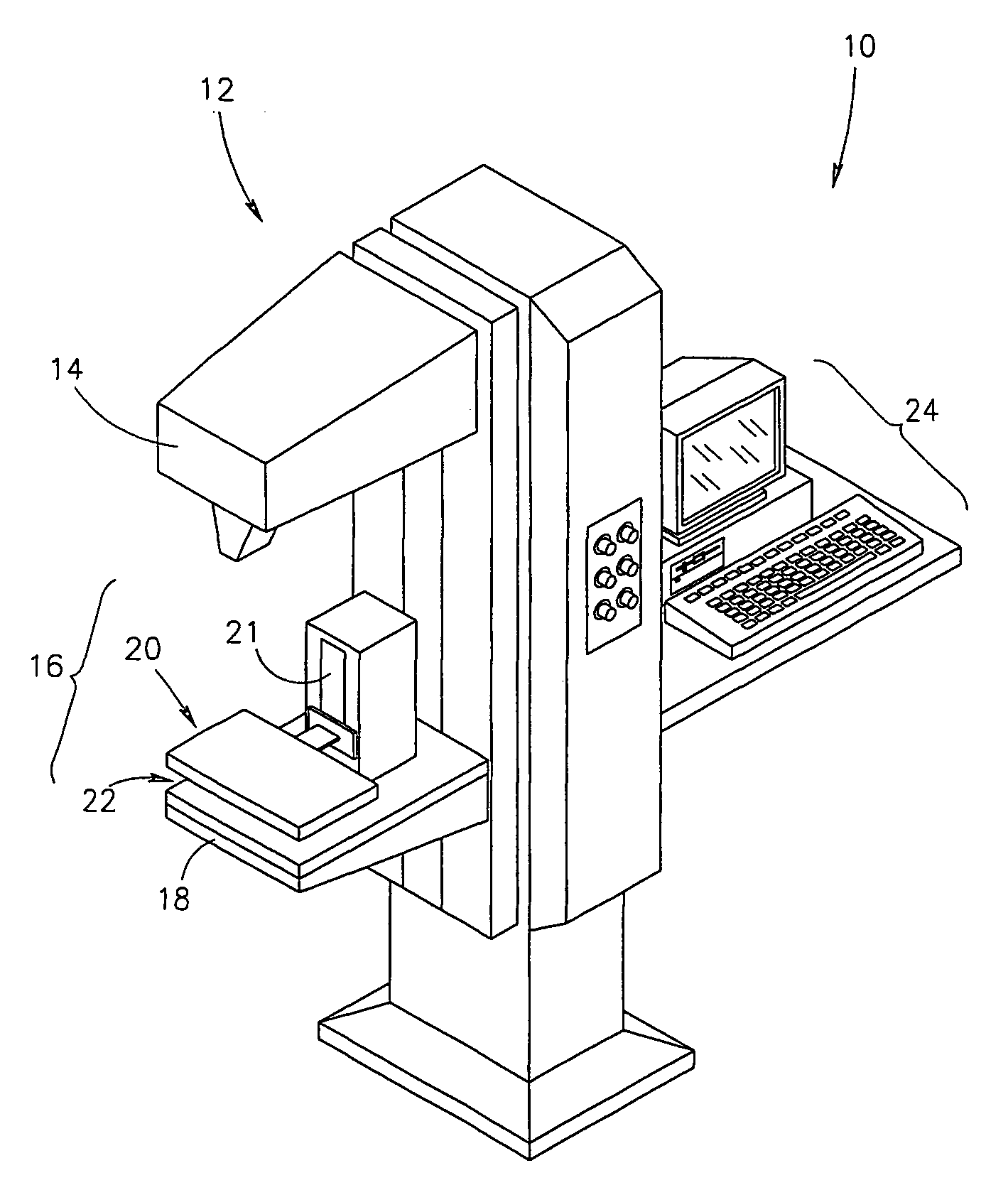
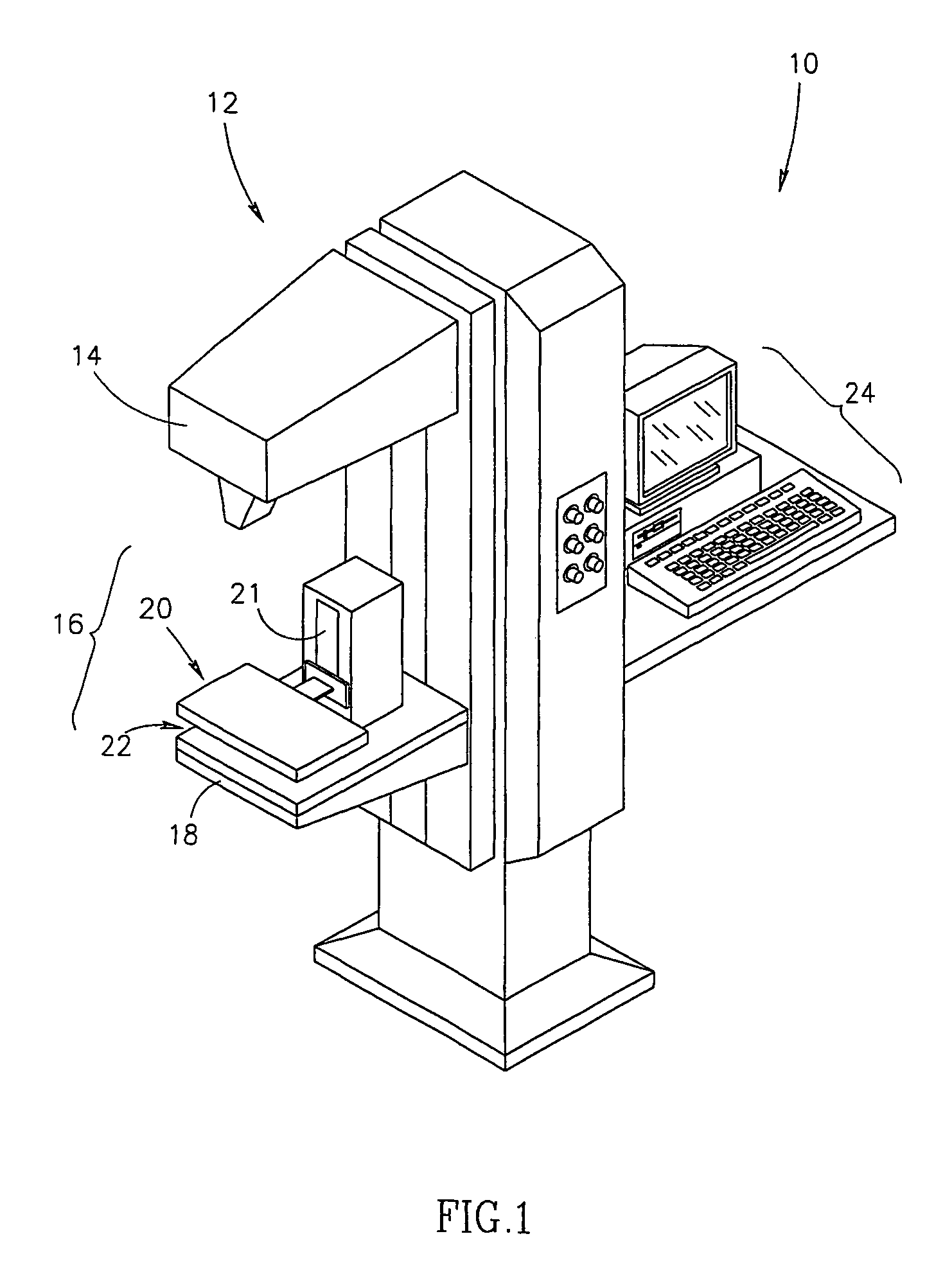
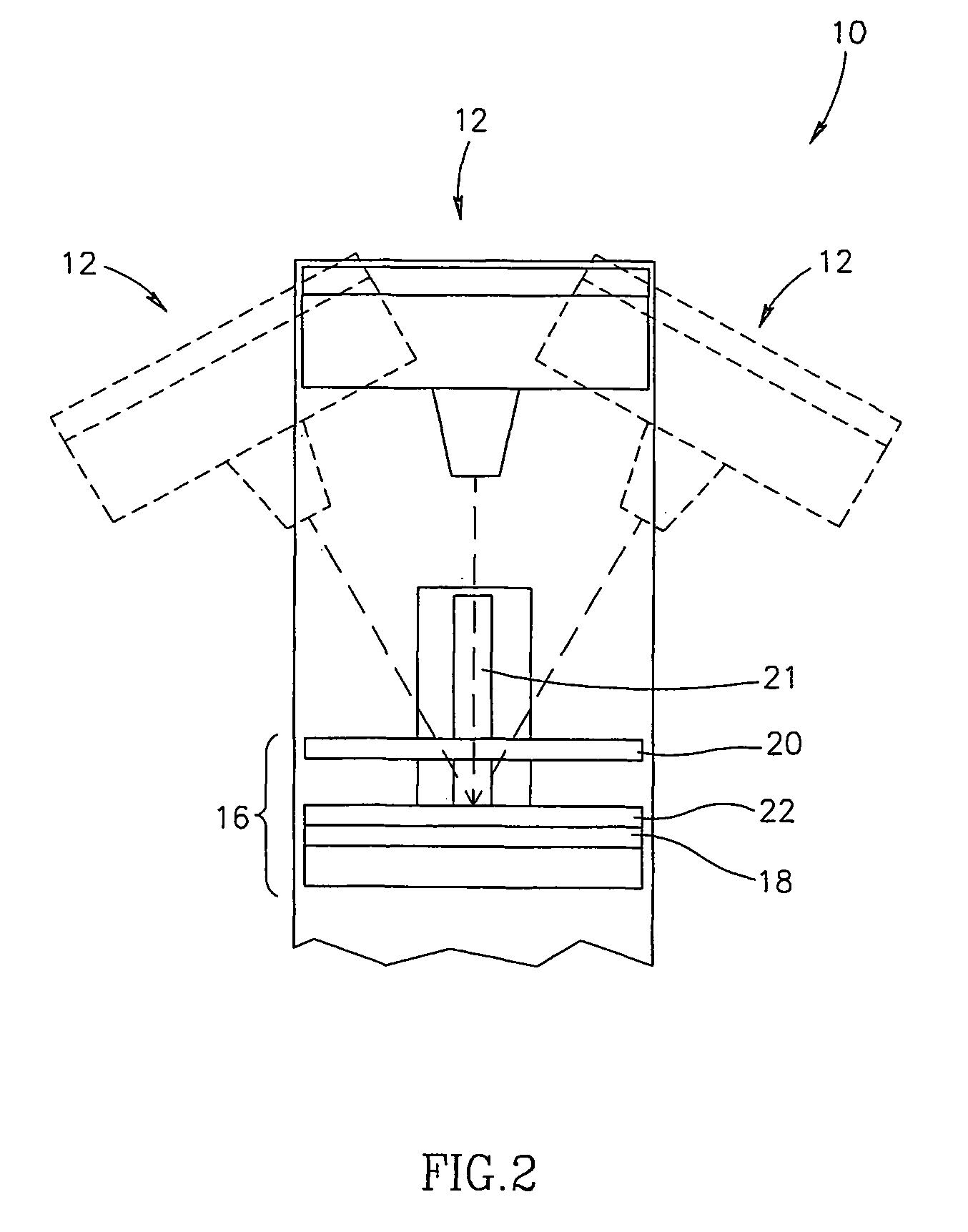
[0147]Reference is now made to FIG. 3A, which is a schematic illustration of dual-purpose apparatus 30 for mammography and impedance-imaging, in accordance with an embodiment of the present invention. As shown, dual-purpose apparatus 30 comprises mammogram 32, which includes a head 12, an x-ray tube 14, a base 16, a compression plate 20 adapted to travel, for example, on a gantry 21, a support plate 22, an image receptor 18 (which may be digital) and optionally, a computer 24. Dual-purpose apparatus 30 generally further comprises at least one impedance probe 40. Optionally, impedance probe 40 is a multi-element impedance probe.

[0148]In some embodiments of the invention, dual-purpose apparatus 30 comprises, in a permanent configuration, x-ray apparatus 32 and at least one impedance probe 40. For example, at least one impedance probe 40 may be comprised in either compression plate 20 as illustrated in FIG. 3A, and / or in support plate 22. In FIG. 3A, impedance probe 40 itself serves as...


PUM


Abstract

Multi-element impedance probe apparatus (40), adapted to produce an image of a body tissue, having a structure, comprising: a raster of sensors (43), comprised of a substantially radiolucent, conductive material; substantially radiolucent conductive wiring (44), forming conductive connections with the sensors; and a substantially radiolucent substrate (46), on which the sensors are mounted.

Description

RELATED APPLICATIONS[0001]This application is a U.S. national filing of PCT Application No. PCT / IL00 / 00287, filed May 21, 2000, the disclosure of which is incorporated herein by reference.FIELD OF THE INVENTION[0002]The present invention relates generally to medical imaging techniques. In particular the present invention relates to performing impedance imaging in conjunction with any of the various forms of x-ray imaging or nuclear imaging.BACKGROUND OF THE INVENTION[0003]In Conventional x-ray radiography, x-rays from a nearly point source are directed on the part of the body (organ) to be imaged. The x-rays emerging from the organ are detected to form a two-dimensional image, producing a shadowgram of the part of the body being imaged. The points on the image have a brightness related to the intensity of the x-rays at that point. Image production relies on the fact that different parts of the anatomy absorb different amounts of x-rays. At times, it is necessary to enhance the x-ray...

Claims


Application Information

Patent Timeline
09 Aug 2005
Publication
US6928315B1
IPC
A61B5/053; A61K49/04; A61K51/00; A61B6/04; A61B6/00
CPC
A61B5/0536; A61B6/0414; A61B6/502; A61B6/5235; A61K49/0433; A61K51/00; A61B6/4258; A61B2562/0209
Inventors
NACHALIEL, EHUD