Guaranteed data synchronization

Inactive Publication Date: 2005-08-09
GLOBALFOUNDRIES INC
View PDF11 Cites 39 Cited by
  • Summary
  • Abstract
  • Description
  • Claims
  • Application Information

AI Technical Summary

Benefits of technology

[0012]The guaranteed data synchronization may occur in a synchronization mode. The synchronization mode may be enabled when it is necessary to ensure that data is read from the memory a certain number of locations (and thus pointer cycles) behind when it is written. The synchronization mode may be useful when it is desired to prevent the effects of clock cycle slippage from affecting data transmissions. For example, the synchronization mode may be particularly useful during the testing of an integrated circuit in which the data synchronization unit is implemented, as it may ensure that responses to test vectors have sufficient setup and hold time to be properly read, and are read at the proper times. Operating in the synchronization mode may also ensure that each unit of a specific integrated circuit design will power up with a known relationship on an integrated circuit tester, thereby allowing test programs to be written with test vectors based on this known relationship.

Problems solved by technology

Furthermore, it is often times possible the within a processor or an I / O bridge, multiple functional units may be present which require differing clock frequencies.
However, this is not a straightforward process when the clock frequencies from one domain to another are different.
This problem may be referred to as cycle slippage, and ICs having multiple clock domains may be particularly vulnerable.
Reading the data at inappropriate times may cause an otherwise good part to fail when tested.
These false failures may in turn lead to good parts being scrapped and the resultant cost of replacement parts.

Method used


Image

  • Guaranteed data synchronization
  • Guaranteed data synchronization
  • Guaranteed data synchronization

Examples


Embodiment Construction

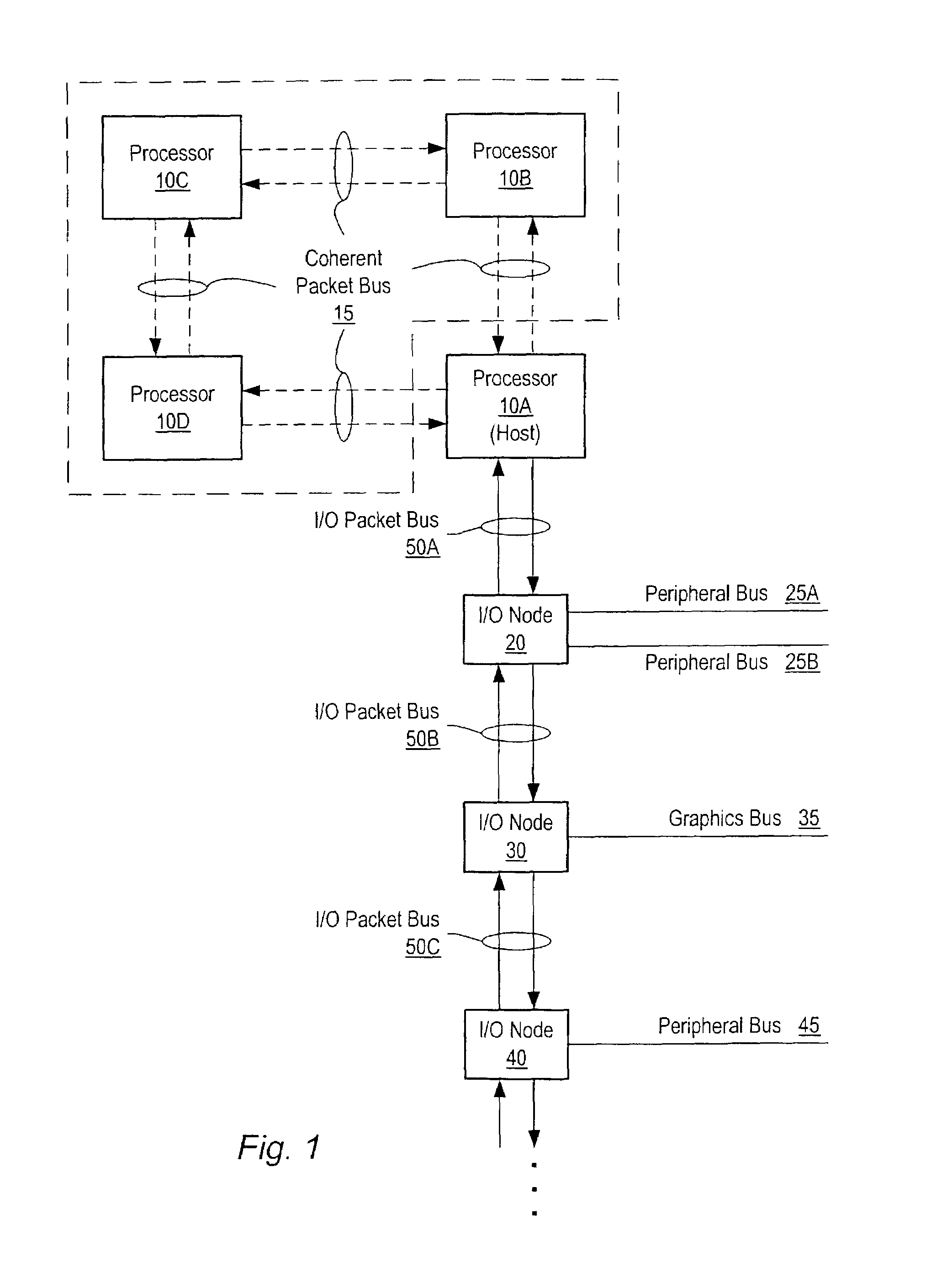
[0021]Turning now to FIG. 1, a block diagram of one embodiment of a computer system is shown. The computer system includes processors 10A–10D each interconnected by a coherent packet bus 15. Each section of coherent packet bus 15 may form a point-to-point link between each of processors 10A–D. While four processors are shown using point-to-point links it is noted that other numbers of processors may be used and other types of buses may interconnect them. The computer system also includes three I / O nodes numbered 20, 30 and 40 each connected together in a chain by I / O packet buses 50B and 50C respectively. I / O packet bus 50A is coupled between host node / processor 10A and I / O node 20. Processor 10A is illustrated as a host node which may include a host bridge for communicating with I / O packet bus 50A. Processors 10B–D may also include host bridges for communication with other I / O packet buses (not shown). The communication links formed by I / O packet bus 50A–C may also be referred to a...


PUM


Abstract

A method and apparatus for guaranteed data synchronization. In one embodiment, a data synchronization unit includes a memory unit, a write pointer unit, a read pointer unit, and synchronization pulse logic. The memory unit may receive information from a source external to the data synchronization unit. The write pointer may specify an address within the memory where incoming information is to be written. A read pointer outgoing information is to be read from. The data synchronization unit may also include synchronization pulse logic. The synchronization pulse logic may be configured to, in a synchronization mode, to generate a synchronization pulse. In response to an assertion of the synchronization pulse, the read pointer may be initialized such that data read out of the memory unit is valid (i.e. guaranteed to meet electrical requirements) at that time.

Description

BACKGROUND OF THE INVENTION[0001]1. Field of the Invention[0002]This invention relates to the transferring of information in an electronic circuit, and more particularly, to the synchronization of information transferred between different clock domains.[0003]2. Description of the Related Art[0004]In a typical computer system, one or more processors may communicate with input / output (I / O) devices over one or more buses. The I / O devices may be coupled to the processors through an I / O bridge which manages the transfer of information between a peripheral bus connected to the I / O devices and a shared bus connected to the processors. Additionally, the I / O bridge may manage the transfer of information between a system memory and the I / O devices or the system memory and the processors.[0005]With multiple processors, multiple I / O devices, and multiple I / O bridges may come multiple clock domains. Often times, the clock frequencies required for operation of the processor, the I / O bridges, and ...

Claims


Application Information

Patent Timeline
IPC IPC(8): G06F12/06G06F13/40H04L7/02H04L12/46
CPCG06F13/4059H04L7/02H04L12/4625H04L7/005
Inventor HEWITT, LARRY D.
Owner GLOBALFOUNDRIES INC
Why Eureka
Try Eureka