Roller cage assembly

a technology of roller cage and assembly, which is applied in the direction of portable power tools, coatings, and artistic surface treatment, can solve the problems of heavy and cumbersome manipulation of roller cage assemblies during use, and achieve the effects of less susceptible to paint degradation, greater ease of rotation, and easy cleaning

Inactive Publication Date: 2005-08-16
DOVE MICHAEL J
View PDF33 Cites 11 Cited by
  • Summary
  • Abstract
  • Description
  • Claims
  • Application Information

AI Technical Summary

Problems solved by technology

The sealed inner cavity excludes paint or other liquids from entering and becoming trapped inside the roller cage assembly, which would cause the roller cage assembly to become heavy and cumbersome to manipulate during use.

Method used


Image

  • Roller cage assembly
  • Roller cage assembly
  • Roller cage assembly

Examples


Embodiment Construction

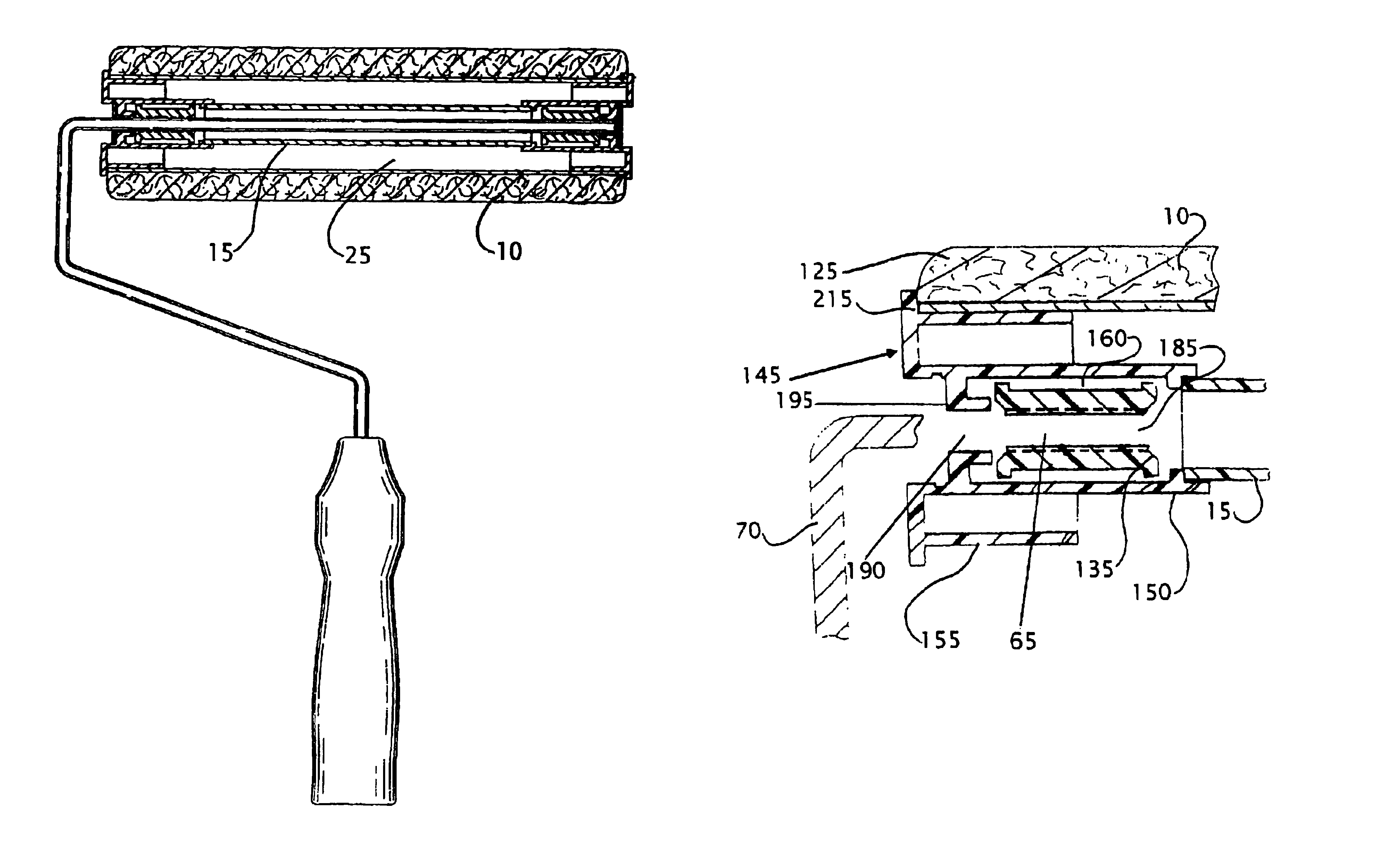
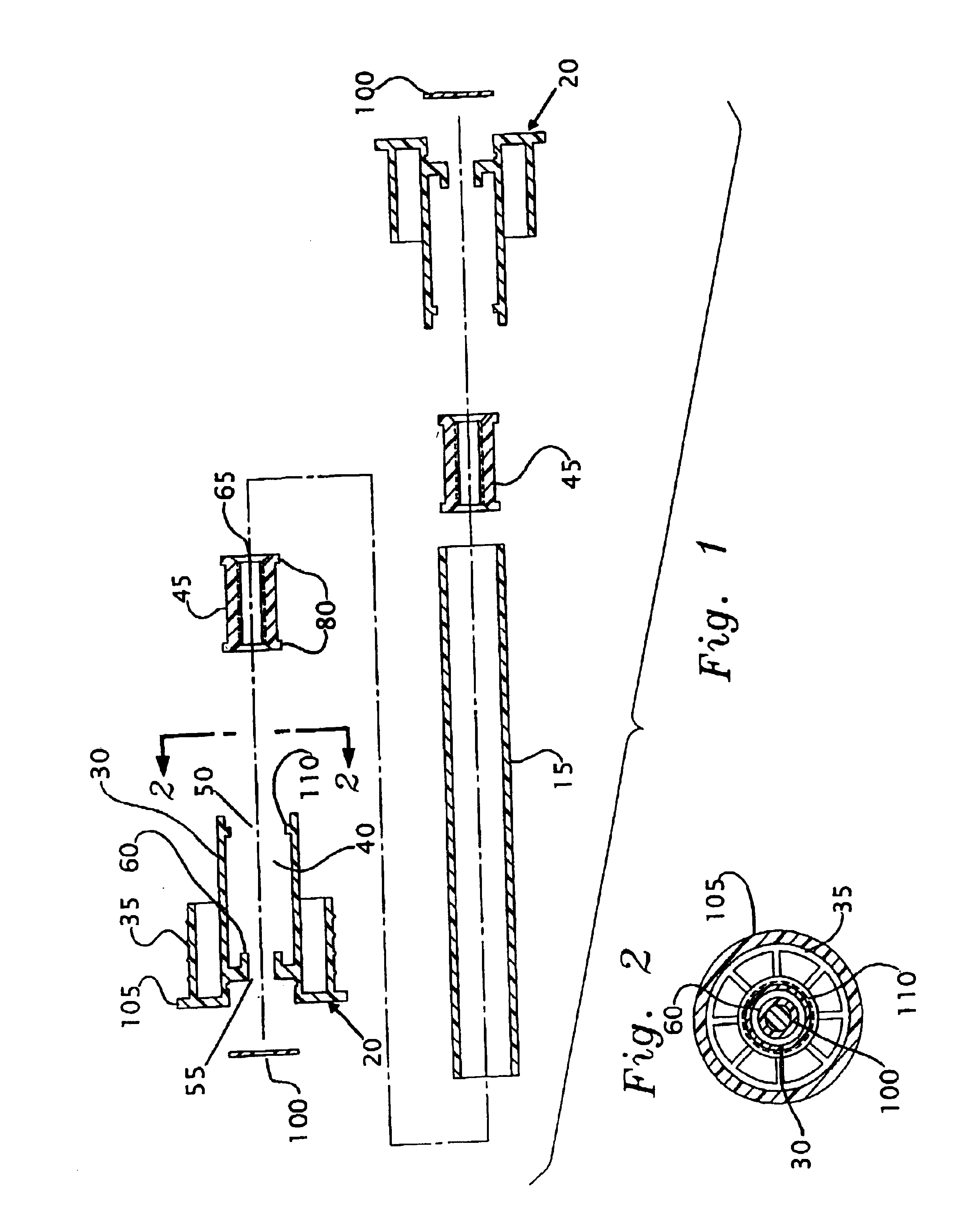
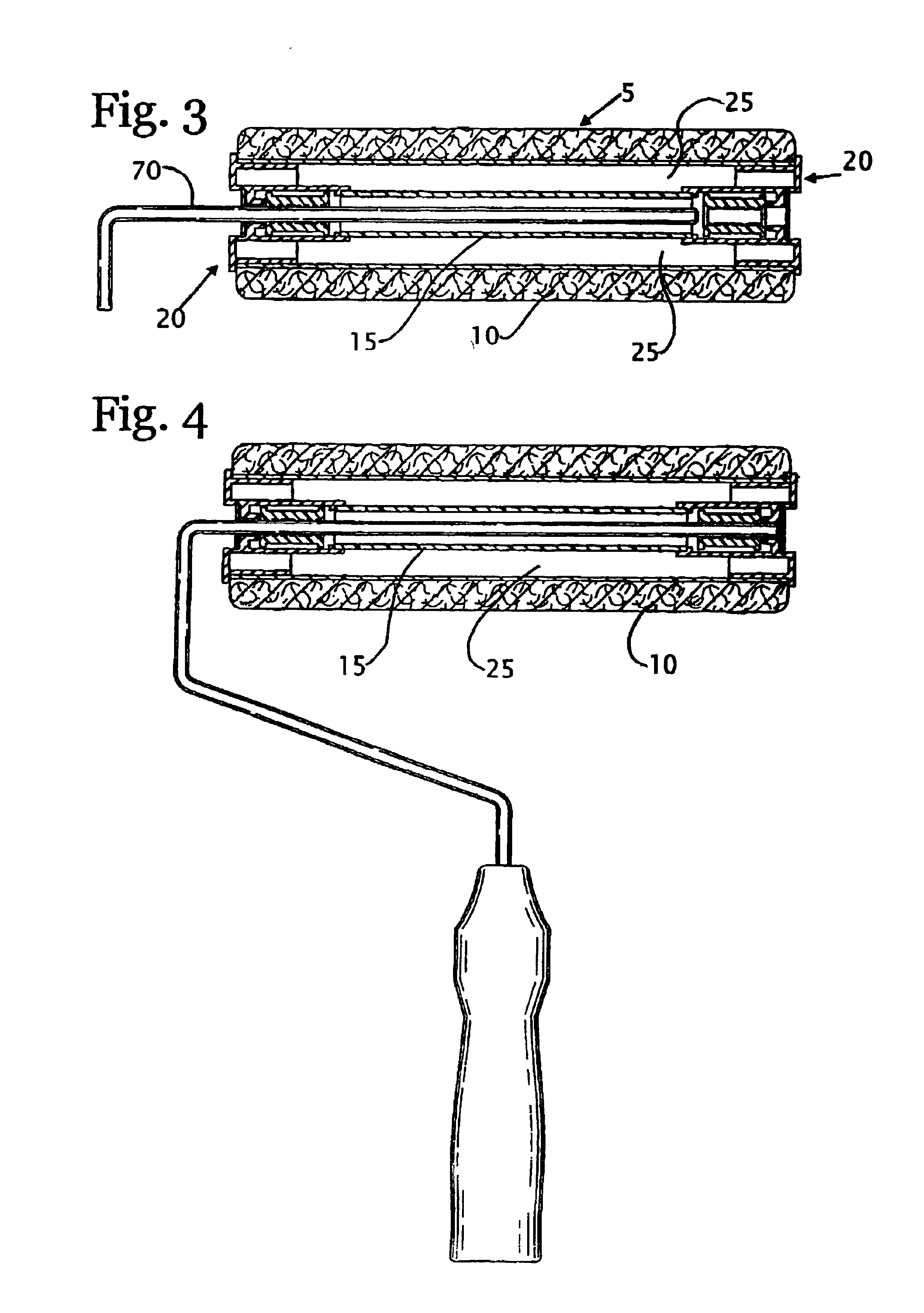
[0028]The present invention describes a roller cage assembly capable of applying liquids to a surface. The roller cage assembly is less susceptible to paint degradation, provides greater ease of rotation, is easier to clean, and is more economical to produce than known devices. The roller cage assembly includes a roller sleeve, a pair of end hub members, and a tube, all for use with a support rod. Each end hub member has an inner hub, an outer hub, a cavity, and a keeper within the cavity. Each cavity receives and allows rotational movement of a corresponding keeper. Each cavity has a slightly reduced outer aperture defined by an L-shaped annular tab to facilitate rotational movement of its keeper. Each keeper has a passage for receiving a support rod, an expandable gap for securing the support rod, and slip ridges to facilitate rotational movement of the keeper within the cavity. The keepers also typically include a joined slit membrane for maintaining a substantially constant degr...


PUM


Abstract

A roller cage assembly for use with a support rod is described. The roller cage assembly has a roller sleeve, a pair of end hub members, and a tube for use with a support rod. Each end hub member has an inner hub, an outer hub, a cavity, and a keeper. Each cavity receives and allows rotational movement of a corresponding keeper. Each cavity has a slightly reduced outer aperture defined by an annular tab to facilitate rotational movement of the keeper. Each keeper has a passage for receiving the support rod, an expandable gap for securing the support rod, and slip ridges to facilitate rotational movement of the keeper. Each keeper also typically has a joined slit membrane for maintaining a substantially constant degree of tension on the support rod. The tube is connected between the inner hub of each end hub member, and the roller sleeve is connected between the outer hub of each end hub member. The roller sleeve, each end hub member, and the tube form an integral unit and are arranged to define a sealed inner cavity, whereby liquid transfer into the inner cavity is substantially prevented.

Description

[0001]This application is a continuation-in-part of application Ser. No. 10 / 276,533, filed 13 Nov. 2002 and now U.S. Pat. No. 6,851,155, which is a national stage application of International Application No. PCT / US02 / 11057, filed 9 Apr. 2002.[0002]The contents of each of the aforementioned applications, and each U.S. Patent and other reference, if any, cited in this application, are hereby incorporated herein by reference.FIELD OF INVENTION[0003]The present invention relates generally to a roller cage assembly. More particularly, the present invention relates to a paint roller cage assembly that forms a sealed inner cavity whereby liquid contamination of the inner roller cavity is substantially prevented. End hub members are adapted to facilitate rotational movement of the paint roller cage assembly during its intended use.BACKGROUND OF INVENTION[0004]Liquid applicators such as paint rollers have come into widespread use due to their ability to apply coatings, usually paint, economi...

Claims


Application Information

Patent Timeline
Patent Type & Authority Patents(United States)
IPC IPC(8): B05C17/02
CPCB05C17/02
Inventor DOVE, MICHAEL J.
Owner DOVE MICHAEL J
Why Eureka
Try Eureka