Fixed line head for flexible line rotary trimmers

a flexible line and rotary trimmer technology, applied in the field of cutting heads, can solve the problems of time and effort of operators, lack of flexibility, and resistance to advancement, and achieve the effects of simple construction, simplified line removal and replacement, and simple structur

Inactive Publication Date: 2005-08-16
PROULX MFG
View PDF18 Cites 53 Cited by
  • Summary
  • Abstract
  • Description
  • Claims
  • Application Information

AI Technical Summary

Benefits of technology

[0011]It is therefore the principal object of the present invention to provide a cutting head for flexible line rotary trimmers that simplifies line removal and replacement while providing a tight securement of the line to the head independent of the rotational velocity of the head.
[0012]It is another object of the present invention to provide a cutting head for flexible line rotary trimmers that simplifies line removal and replacement which is of simple construction and economical to manufacture.
[0013]It is still another object of the present invention to provide a cutting head for flexible line trimmers that simplifies line removal and replacement and is adapted for use in heavy brush.
[0014]It is a further object of the present invention to provide a cutting head for flexible line rotary trimmers that simplifies line removal and replacement while providing a tight securement of the line to the head independent of the rotational velocity of the head and is adaptable for use with cutting line of varying diameters.
[0015]It is yet another object of the present invention to provide a cutting head for flexible line rotary trimmers that simplifies line removal and replacement without the need for any disassembly.

Problems solved by technology

While this evolution of the flexible line rotary trimmers from the manual head to the automatic head has significantly reduced operator time and effort in replacing worn and broken line, these advancements have met with some resistance.
For the casual home user this can present a problem.
If this is not done properly, the line may tangle within the head, interfering with the withdrawal of fresh line and requiring disassembly of the head and rewinding of the line.
The more complicated the line feed mechanism, the more critical is the proper winding of the line within the head.
While such a head and line configuration provides for relatively simple line replacement, each length of replacement line must be provided with a suitable enlarged member at one end thereof, significantly increasing the cost of operation.
In addition, if the cutting line were to break at the eyelet or outlet end of the line channel, line removal may be difficult.
Accordingly, when such a head is used in heavy brush, the drag on the line will cause the rotational speed of the head to drop, decreasing the centrifugal force acting on the cams and thus the gripping forces of the cams against the lengths of line.
As a result, the line could be pulled from the head by the brush, rendering the head ill-suited for use in heavy brush.
The extension of the securement mechanism beyond the surface of the head renders the mechanism susceptible to becoming entangled during use which would tend to pull the mechanism outwardly from the head and possibly release the cutting line at a relatively high velocity.
Thus, while this embodiment of a fixed line head is not dependent on rotational velocity for its gripping force, it also is ill-suited for use in heavy brush.

Method used


Image

  • Fixed line head for flexible line rotary trimmers
  • Fixed line head for flexible line rotary trimmers
  • Fixed line head for flexible line rotary trimmers

Examples


second embodiment

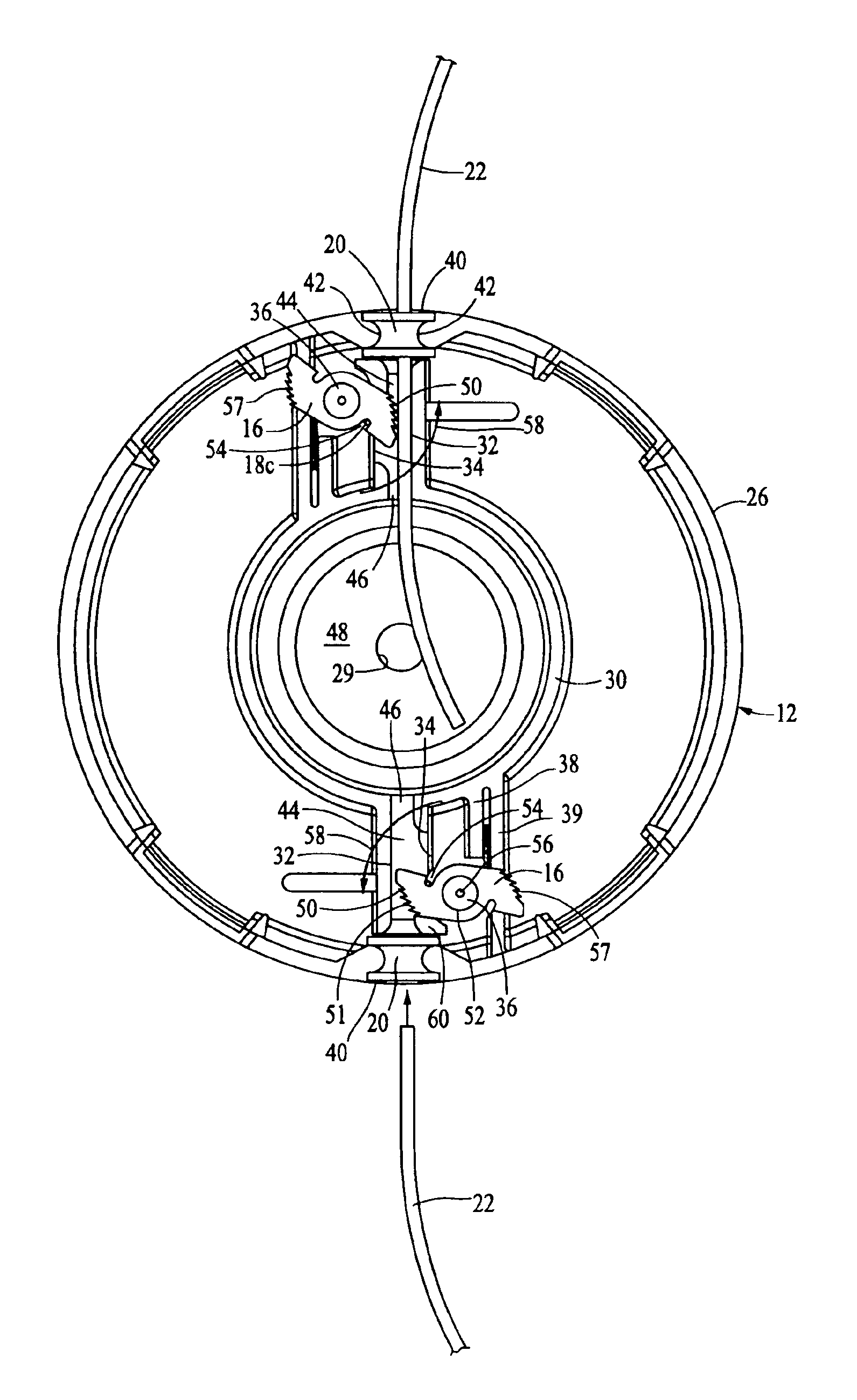
[0043]In an improved second embodiment, the lower cover 14 is additionally provided with arcuate walls 75a and 75b disposed on opposite sides of the annular projections 68 with walls 75a merging into wall portion 74 and arcuate walls 75b being connected to projection 68 via webs 77 as seen in FIG. 11. The upper surfaces of arcuate walls 75a and 75b are coplanar with the end surfaces 70 of projections 68 and thus bear against and help maintain the cams 16 in a horizontal disposition within head 10. Small arcuate relief areas 68a are provided in interior facing surfaces of projections 68 to accommodate the vertical leg portions 18c of torsion springs 18.

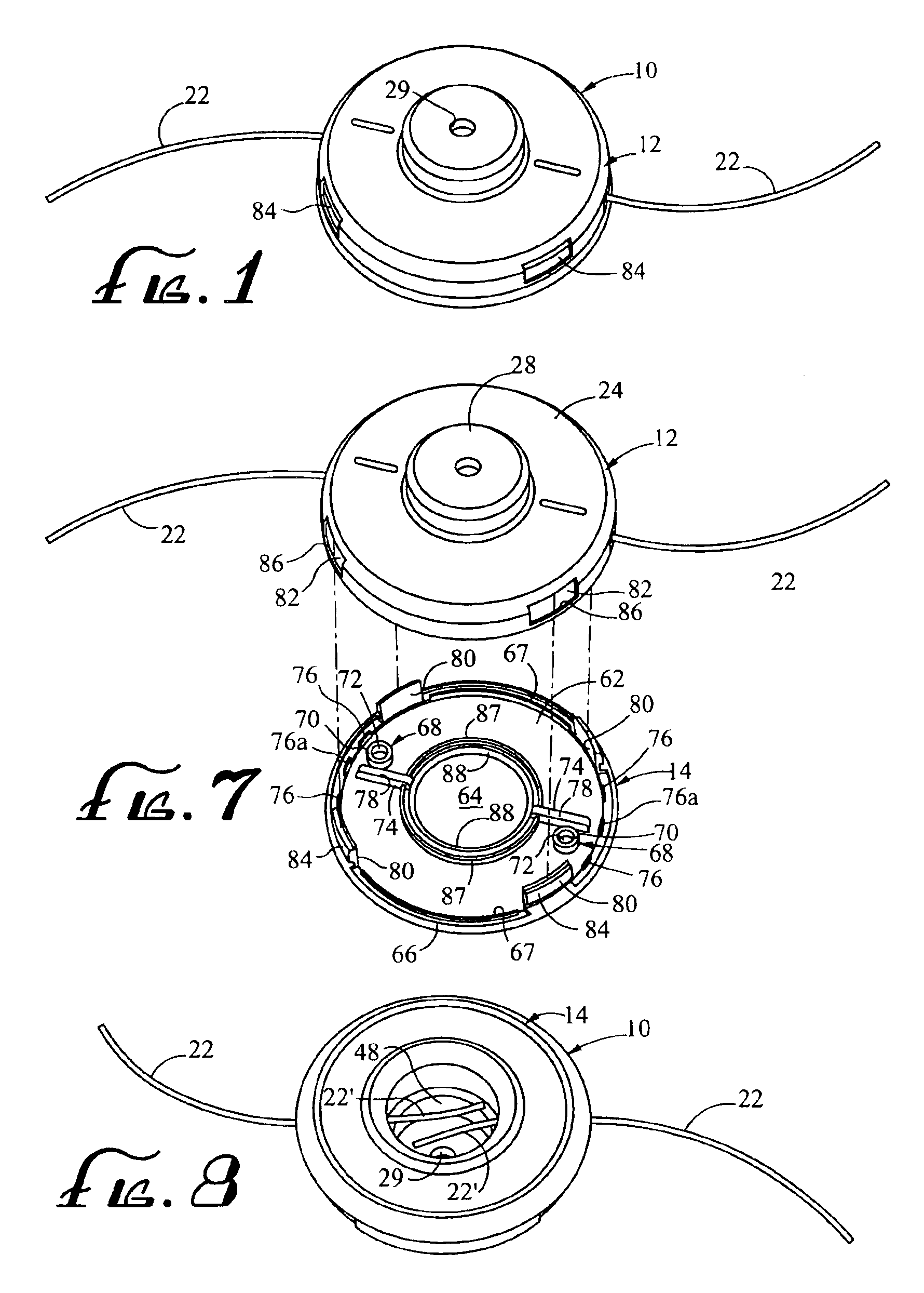
[0044]To secure the lower cover 14 to the housing 12, the cover is provided with a plurality of axially extending resilient locking tabs 80 that are adapted to be received in openings 82 formed in the perimeter wall 26 of housing 12. Tabs 80 are each provided with an outwardly projecting tapered portion 84, as seen in FIG. 9, so that w...

first embodiment

[0058]The particular angular orientations of the individual teeth on cam 116 are illustrated in detail in FIG. 14B. In that regard it should be noted, that the pointed line engagement teeth in cam 16 are uniformly spaced along the end surface of the cam and are oriented such that all of the teeth projecting into the adjacent channel 44 project at increasing angles of inclination with respect to the support wall, from the outermost tooth 50a to the innermost blunt tooth 53. In cam 116, the teeth are relatively uniformly spaced apart, however, tooth 150c, while inwardly inclined with respect to the wear resistant surface of support wall 132 is not as inclined with respect to that surface as its outwardly adjacent tooth 150b. Such a configuration has been found to provide excellent line engaging characteristics. In addition, the innermost tooth 150h, which is pointed and not blunt like the innermost tooth on cam 16, is not as inclined with respect to the support wall surface as its inw...


PUM


Abstract

A cutting head for rotary trimmers in which at least one, and preferably two relatively short fixed lengths of flexible cutting line are inserted into opposed channels in the head and are secured in place by a pair of spring biased toothed cams. Each of the cams is pivotally mounted on a post within the housing adjacent one of the channels and defines a curvilinear camming surface having a plurality of uniformly spaced teeth thereon that project into the channels at increasing angles of inclination from the outermost tooth to the innermost tooth for engaging the line. A pair of torsion springs bias the cams to pivot on their mounting teeth such that the backsides of the teeth are continually urged toward the openings to the channels thereby allowing line to be inserted inwardly into the head past the toothed cams but retained by the cams against any outwardly directed forces acting on the line. The cams are symmetrically balanced about their axes of rotation so as to be unaffected by centrifugal force acting thereon during use.

Description

CROSS REFERENCE TO RELATED APPLICATIONS[0001]This is a continuation-in-part of application Ser. No. 10 / 314,674 entitled “FIXED LINE HEAD FOR FLEXIBLE LINE ROTARY TRIMMERS” filed Dec. 9, 2002, now abandoned, which is a continuation-in-part of application Ser. No. 09 / 992,048, filed Nov. 21, 2001, now U.S. Pat. No. 6,519,857, issued on Feb. 18, 2003.BACKGROUND OF THE INVENTION[0002]The present invention is directed to cutting heads for use in flexible line rotary trimmers. Flexible line rotary trimmers are commonly used for cutting vegetation such as grass and weeds, particularly along walks, fences and flower beds and around trees. These devices comprise a rotary driven head that carries one or more lengths of monofilament line mounted within a housing. Extended end portions of each line project from the housings through guides in the side wall of the housing. As the head rotates at high speed, the end portions of the line are caused to project outwardly from the housing by the centri...

Claims


Application Information

Patent Timeline
Patent Type & Authority Patents(United States)
IPC IPC(8): A01D34/416A01D34/412
CPCA01D34/4166
Inventor PROULX, RICHARD A.JOHNSON, SASHA
Owner PROULX MFG
Why Eureka
Try Eureka