Method and apparatus for measurement of flow rate

Inactive Publication Date: 2005-08-16
PEARSON JOHN J
View PDF5 Cites 46 Cited by
  • Summary
  • Abstract
  • Description
  • Claims
  • Application Information

AI Technical Summary

Benefits of technology

[0021]It is another object of the present invention to provide a new and improved flow meter that creates minimal disturbance to the flow through the bounded path.
[0022]A further object or feature of the present invention is a new and improved flow meter that minimizes the effects of therma

Problems solved by technology

There are numerous problems with these prior designs, including, but not limited to, the following:1. The most important criteria when observing something is to do so without disturbing the object being observed.
This is the worst place to disrupt a flow path, and creates undesired turbulence.
Turbulence usually adversely affects the performance of the flow measuring device and all supporting equipment (e.g., electronic pressure transducers).2. As the temperature of the gas flow increases or decreases, the size of the bounded path may increase or decrease by thermal expansion of the materials used.
.), structural failure may result from unequal expansion of boundaries and connecting structures.
Bowers addresses this e

Method used


Image

  • Method and apparatus for measurement of flow rate
  • Method and apparatus for measurement of flow rate
  • Method and apparatus for measurement of flow rate

Examples


Embodiment Construction

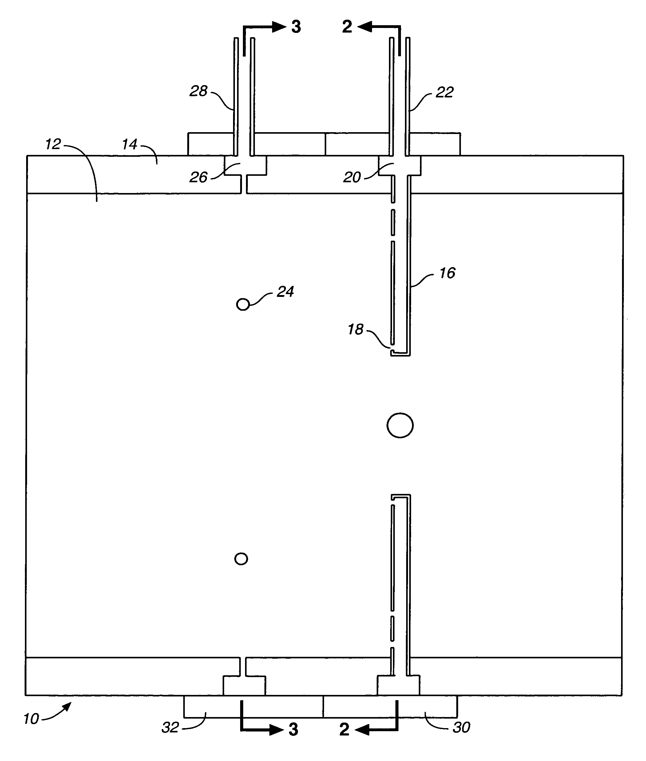
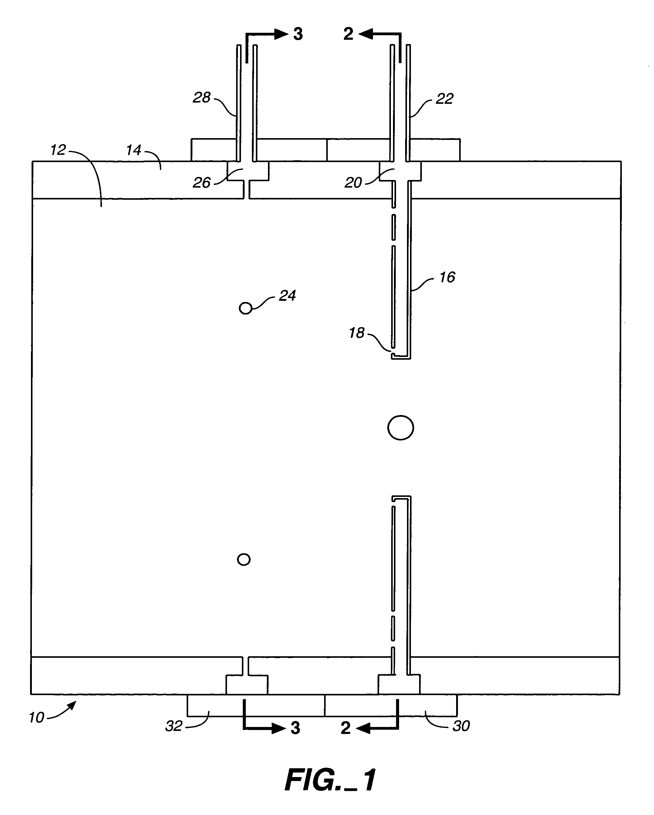
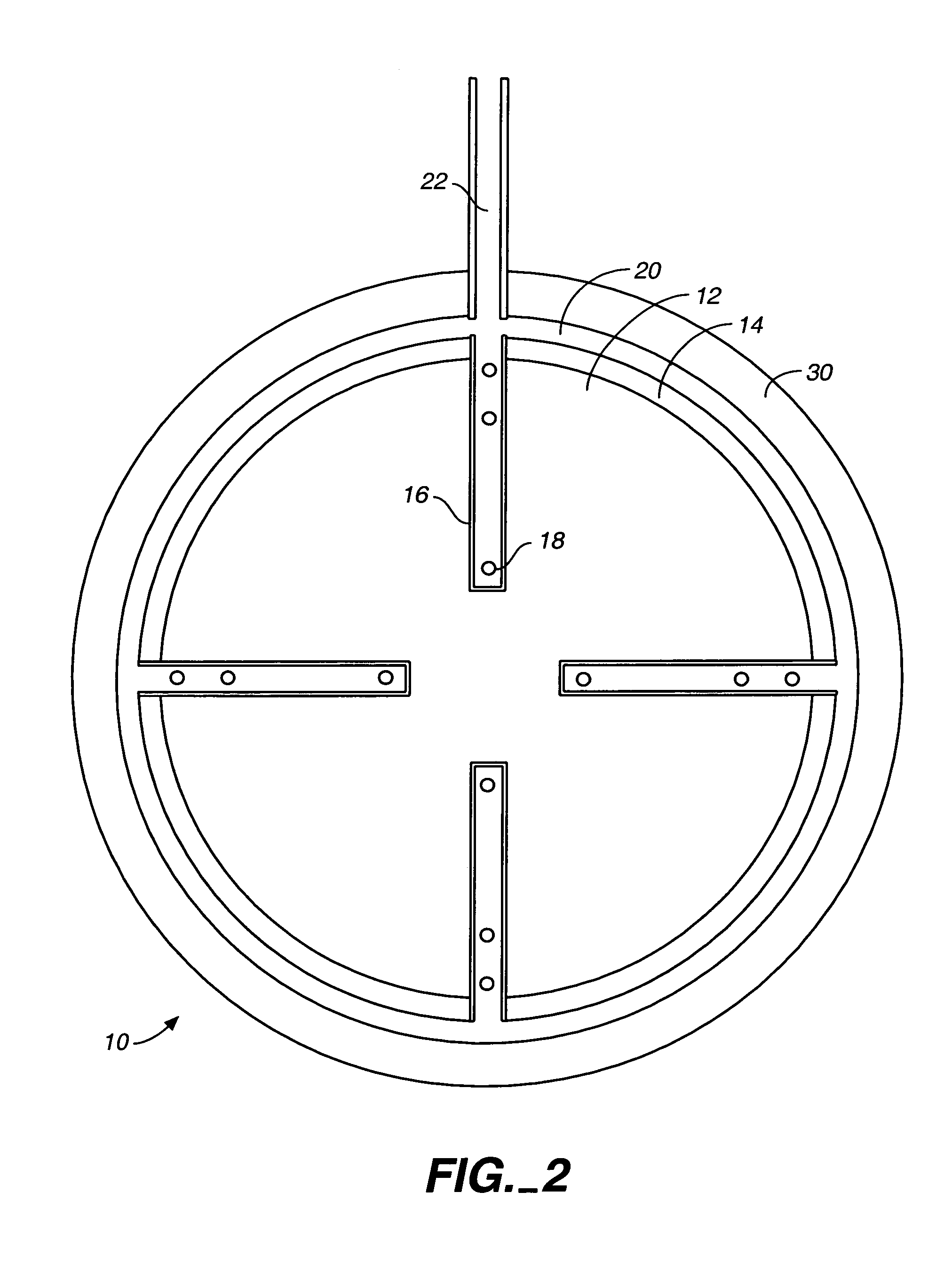
[0050]Referring to FIGS. 1 through 17, wherein like reference numerals refer to like components in the various views, there is illustrated therein a new and improved apparatus for measurement of flow rate, generally denominated 10 herein.

[0051]Referring to FIGS. 1–3, a typical example of a flow meter 10 comprises a hollow body herein referred to as a bounded path 12, bounded by walls 14. Velocity sensing stalks comprising semi-traversing sensing tubes 16 extend into the flow path in an semi-traversing fashion, and detect gas pressure created by the velocity of the gas, herein referred to as sensing pressure, through a plurality of apertures 18. The sensing tubes are in fluid communication by means of an external connecting conduit, plenum or channel 20 where the total average sensing pressure is accumulated and finally measured through a total average sensing pressure port 22.

[0052]The bounded path includes reference pressure ports 24 within the walls 14 of the path 12 that conduct ...


PUM


Abstract

A bi-directional, clean or grey medium, wide temperature range, low intrusion, low turbulence, mass flow meter extends multiple pressure sensing tubes, each containing multiple pressure sensing ports, into a bounded path a distance no more than one half the diameter of the path, or semi-traversing. These sensing tubes sense impact or static pressures to obtain a sensing pressure, and are in fluid communication with a channel located externally of the bounded path which provides a total average sensing pressure for measurement. A series of reference pressure ports are located flush to the wall surface of the bounded path to obtain a reference pressure. These reference ports are in fluid communication with another channel located externally of the bounded path which provides a total average reference pressure for measurement. The difference in total average sensing pressure and total average reference pressure can be measured and used to calculate the average velocity and volume of gas within the bounded path. Alternatively, the difference in total average pressures can produce a measurable sample flow through a channel connecting the two total average pressure plenums, which is proportional to the flow through the bounded path.

Description

CROSS REFERENCE TO RELATED APPLICATIONS[0001]The present application claims the benefit of the filing date of U.S. Provisional Patent Application Ser. No. 60 / 500,892, filed Sep. 4, 2003.STATEMENT REGARDING FEDERALLY SPONSORED RESEARCH OR DEVELOPMENT[0002]Not applicable.REFERENCE TO A MICROFICHE APPENDIX[0003]Not applicable.TECHNICAL FIELD[0004]The present invention relates generally to flow measuring devices, and more particularly to an improved method and apparatus for the measurement of flow rate. The inventive apparatus is in a class of flow measuring devices referred to as “pressure differential producers” and is based on the Pitot tube, specifically the averaging Pitot tube. An averaging Pitot tube contains a plurality of sensing ports on a single tube.BACKGROUND INFORMATION AND DISCUSSION OF RELATED ART[0005]U.S. Pat. No. 1,250,238 to Spitzglass for a Pitot Tube discloses a method of measuring fluids by means of a Pitot tube which transmits the pressure equivalent of the veloc...

Claims


Application Information

Patent Timeline
IPC IPC(8): G01F1/34G01F1/46
CPCG01F1/46
Inventor PEARSON, JOHN J.
Owner PEARSON JOHN J
Why Eureka
Try Eureka