Method and apparatus for cutting tire ply stock

Inactive Publication Date: 2005-08-16
THE GOODYEAR TIRE & RUBBER CO
View PDF36 Cites 27 Cited by
  • Summary
  • Abstract
  • Description
  • Claims
  • Application Information

AI Technical Summary

Benefits of technology

[0015]One advantage of the present invention is that the ply stock can be cut between adjacent cords without severing either cord.
[0016]Another advantage of the present invention is that the ply stock can be severed witho

Problems solved by technology

A disadvantage of these apparatuses is that the two knives must cut between the same pair of adjacent cords.
A disadvantage of this

Method used


Image

  • Method and apparatus for cutting tire ply stock
  • Method and apparatus for cutting tire ply stock
  • Method and apparatus for cutting tire ply stock

Examples


Embodiment Construction

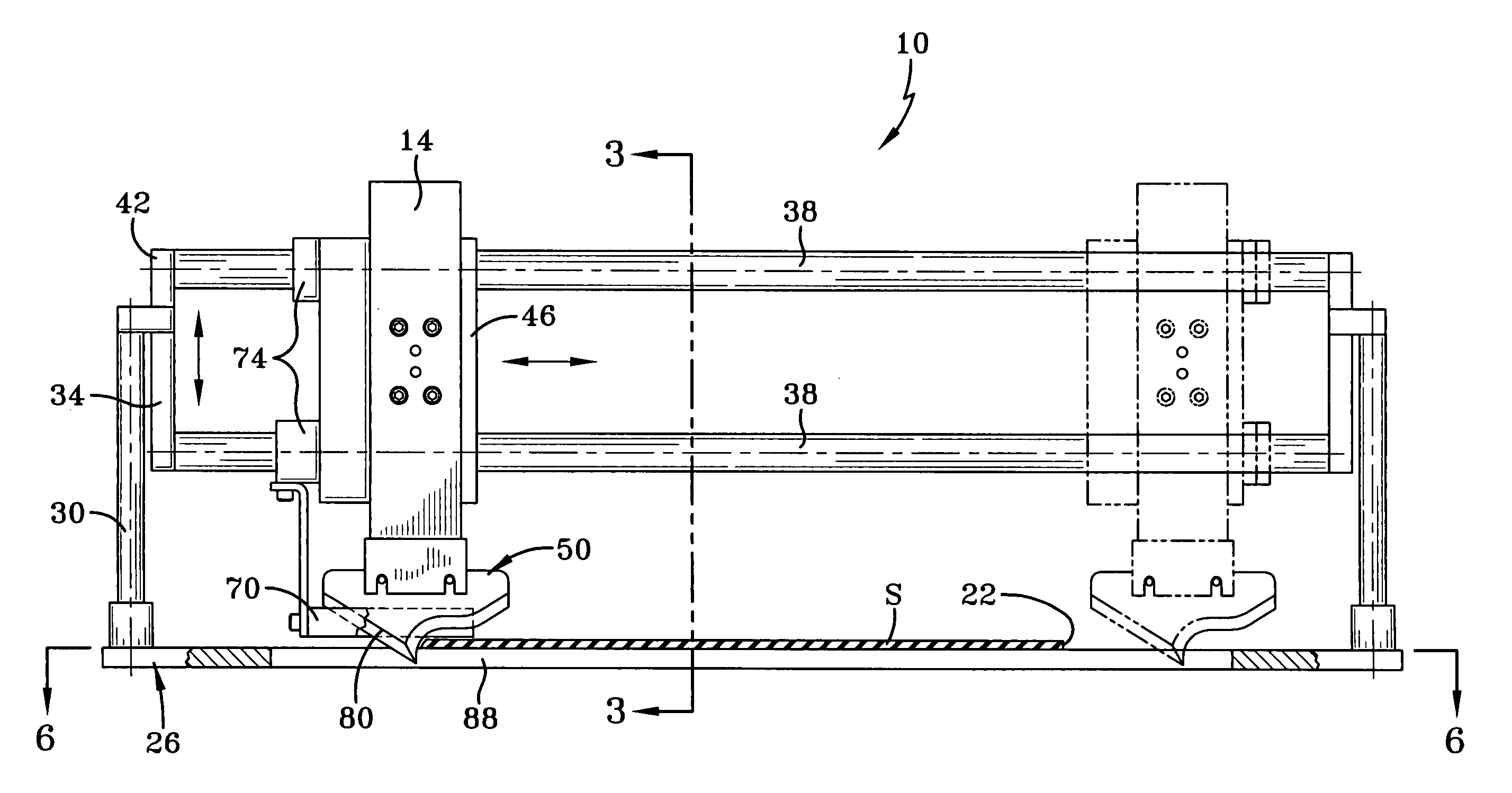
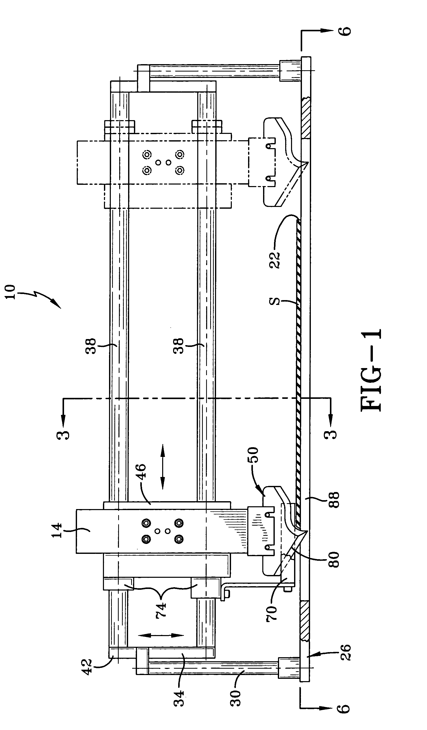
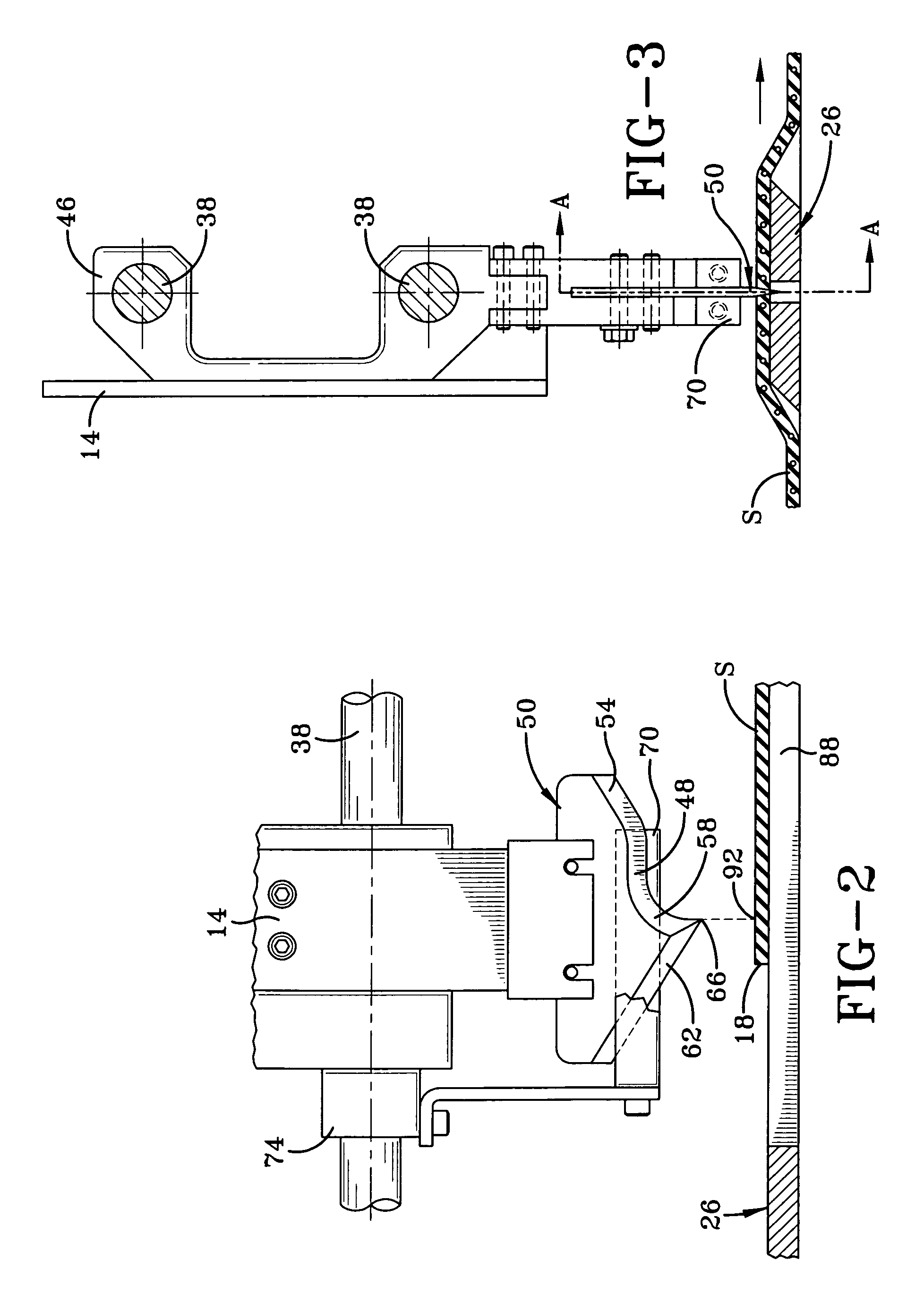
[0028]Referring now to the drawings wherein the showings are for purposes of illustrating a preferred embodiment of the invention only and not for purposes of limiting the same, FIG. 1 shows an apparatus 10 for severing tire building sheet material, referred to herein as ply stock S. The apparatus 10 includes a knife assembly 14 which is mounted to means for moving the knife assembly toward and away from the ply stock to be cut. The apparatus 10 further includes means for moving the knife assembly 14 across the ply stock from a fist lateral edge 18 thereof to a second lateral edge 22. The apparatus 10 also includes an anvil 26 for supporting the ply stock S in the immediate area below a cut line A—A shown in FIGS. 3 and 8. The embodiment of apparatus 10 is shown in FIGS. 1 and 2, and 3 for illustrative purposes only and not by means of limiting the invention. In the preferred embodiment, the apparatus 10 includes a frame 30, an anvil 26, a carrier 34 including guide bars 38 extendin...


PUM

PropertyMeasurementUnit
Areaaaaaaaaaaa
Timeaaaaaaaaaa

Abstract

Method and apparatus for severing tire ply stock (S) wherein the apparatus includes a knife assembly (14) utilizing a blade (50) having a curved leading edge (58) and a straight trailing edge (62) which meet at a leading point (66). The ply stock (S) is supported by a slotted anvil (26) in the area immediately adjacent a cut line. In operation, the knife assembly (14) is lowered and the leading point (66) pierces the ply stock (S) between adjacent cords. During the downward stroke, the trailing edge (62) back-cuts the ply stock (S) from the insertion point (98) to a first lateral edge (18). The leading edge (58) severs the remainder of the ply stocks (S) as the knife assembly (14) traverses the ply stock to a second lateral edge (22).

Description

TECHNICAL FIELD[0001]This invention pertains to methods and apparatus for cutting tire ply stock and the like.BACKGROUND ART[0002]Different apparatus and methods have been utilized in order to provide cut-to-length sections of ply stock used for building tires. In U.S. Pat. Nos. 3,429,490 and 3,641,855, apparatuses which utilize plunging knives are disclosed. In these apparatuses, a pair of knives is used to transpierce the ply stock at the center of the ply. Then each knife is moved to an opposite lateral edge of the ply stock. The cuts are made from the center outward in order to avoid crushing the lateral edges of the ply stock. A disadvantage of these apparatuses is that the two knives must cut between the same pair of adjacent cords.[0003]In U.S. Pat. No. 3,789,712 a single knife blade is used. The blade is moved into a first edge of the ply which is lifted from the conveyor up against a stock support and held there by the oblique cutting edge while the knife blade makes its cu...

Claims


Application Information

Patent Timeline
IPC IPC(8): B26D3/00B26D7/10B26D7/08B26D5/08B26D1/00B26D1/06B29D30/46
CPCB26D1/0006B26D1/065B26D3/003B29D30/46B26D2001/006Y10S83/951Y10T83/0605Y10T83/293Y10T83/8769Y10T83/8822
Inventor RATKUS, JEFFERY RAYMONDCAILLET, ROBERT CHARLES
Owner THE GOODYEAR TIRE & RUBBER CO
Why Eureka
Try Eureka