Tire in with cavities in bead region

a technology of bead region and tire, which is applied in the field of pneumatic tires, can solve the problems of not being design is not compatible with conventional tires or conventional rims, and cannot meet the requirements of widespread acceptan

Inactive Publication Date: 2005-08-16
THE GOODYEAR TIRE & RUBBER CO
View PDF13 Cites 18 Cited by
  • Summary
  • Abstract
  • Description
  • Claims
  • Application Information

AI Technical Summary

Benefits of technology

[0016]The process of installing the tire upon the wheel causes the torus cavity to flatten against the bead seat and the air contained by void spaces defined by the torus cavity and the bead seat to be substantially expelled from the void space creating adherence force via vacuum. The surrounding elastomeric material of the torus cavity provides an air-tight seal preventing air from leaking back into the void spaces defined by the torus cavity and the rim once the tire has been installed in the wheel. The torus cavity may also be flattened or held in a flattened condition against the bead seat by the bead core when the tire is installed on a wheel rim and operated in a normally inflated condition on a vehicle. The torus cavity may also be flattened or held in a flattened condition against the wheel rim by the bead core when the tire is installed on a wheel rim and operated in an inflated or uninflated condition on a vehicle traveling in a straight line and at a constant speed.
[0017]Once the torus cavity has been flattened by installation or operation of the tire, the bead will resist separation from the wheel rim bead seat and resist rotation of the bead region that would tend to lift or separate the bead toe from the rim bead seat.

Problems solved by technology

However, in the design of EMT tires, conventional bead designs have been found inadequate to fully resist the forces on the bead region that occur when the tire is operated in an under-inflated or uninflated condition.
However, most of these designs are not compatible with either conventional tires or conventional rims and have not met with widespread acceptance.

Method used


Image

  • Tire in with cavities in bead region
  • Tire in with cavities in bead region
  • Tire in with cavities in bead region

Examples


first embodiment

Detailed Description of the First Embodiment

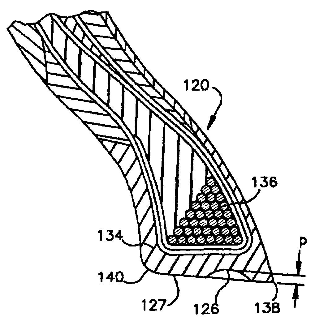
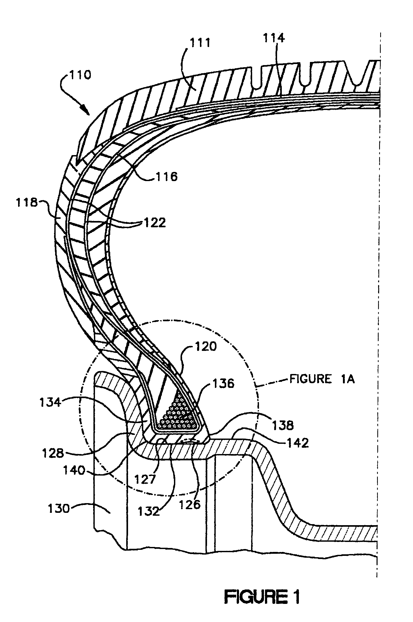
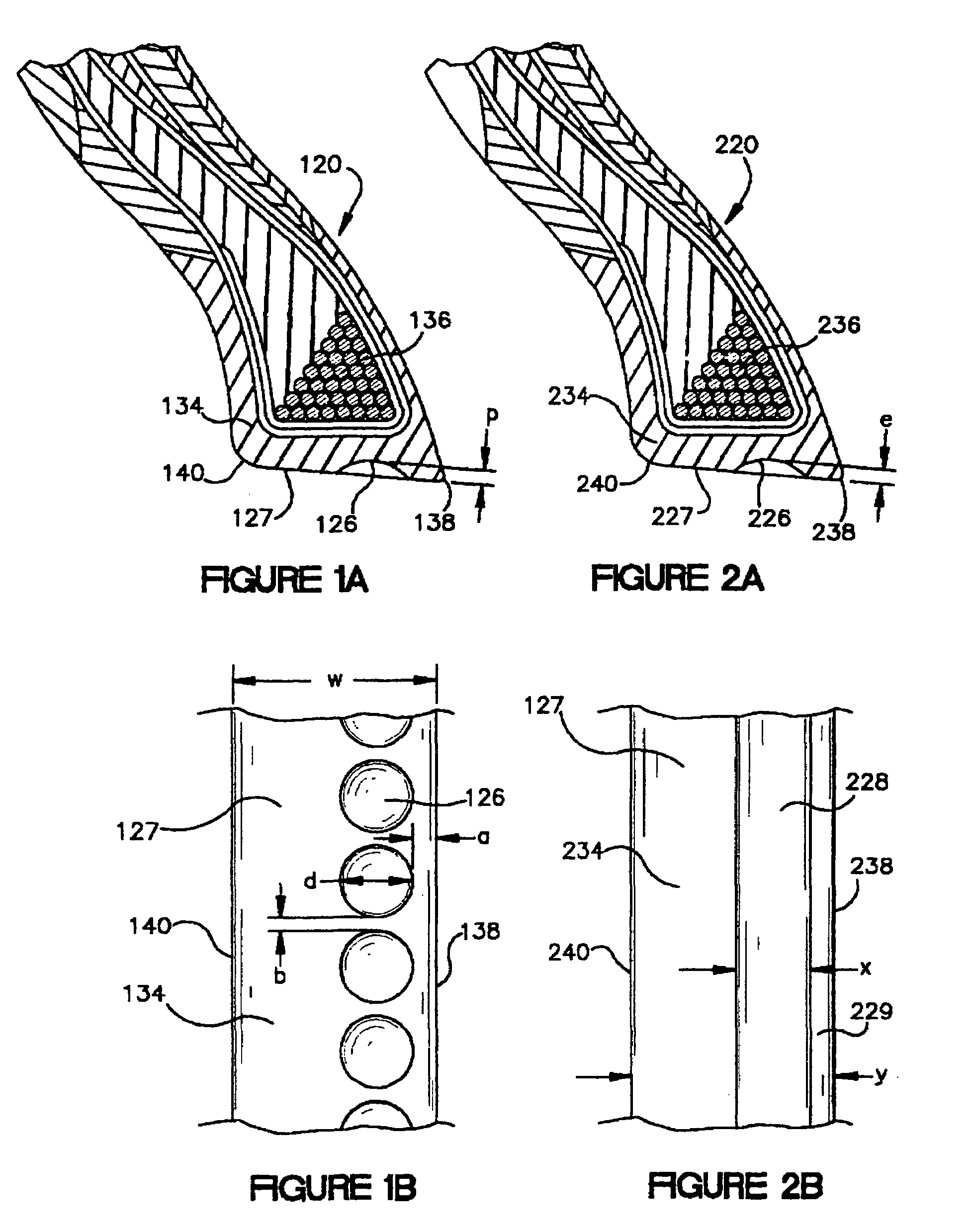
[0057]Referring to FIG. 1, there is illustrated a cross-sectional view of a runflat tire 110 incorporating a series of discrete cavities 126 on the surface of the bead region 120 of the tire in accordance with the first embodiment of the invention. The tire 110 has a tread 112, a belt structure 114, and a carcass structure 116, comprising a pair of sidewalls 118, a pair of bead regions 120, and one or more reinforcing carcass plies 122 anchored in each bead region 120. A series of cavities 126 are located in the surface 127 of the bead region 120 which contacts the wheel rim 128.

[0058]When the tire 110 is installed on a wheel 130, the cavities 126 are flattened against the rim bead seat 132 causing at least a 95 percent reduction in the volume of the cavities and causing the expulsion of about 90 percent of the air contained by the cavities. In addition, the initial size and shape of the cavities 126, the elasticity of the surrounding elas...


PUM


Abstract

The present invention relates to a pneumatic tire, specifically to improvements to the bead region of tires designed for runflat operations. The improvements comprise the addition of cavities or indentation (126) on the surface of the bead (127) that contacts the wheel rim (128). In a first embodiment a series of circular cavities (126) are located on the radial innermost surface of the bead in the proximity of the bead toe. In a second embodiment, a continuous groove-like torus cavity (226) is located in the radially innermost surface of the bead in the proximity of the bead toe. The series of cavities or torus cavity increase the adherence of the bead to the rim as a small volume of air at a low pressure, significantly inferior to the atmospheric pressure (air vacuum situation) is trapped in the void spaces created by the cavities or torus cavity and the bead seat.

Description

TECHNICAL FIELD[0001]The present invention relates to a pneumatic tire, specifically to improvements to the bead region of tires designed for runflat operations.BACKGROUND OF THE INVENTION[0002]An important design consideration in the development of a run-flat tire is insuring that the uninflated tire remains seated on the rim. Solutions have been developed employing bead restraining devices as well as special rims to accomplish this requirement.[0003]The design of the bead region for extended mobility technology (EMT) tires requires the balance of two opposing criteria. The design of the bead region must provide the means for the bead to remain seated on the rim during uninflated operation and the design should be compatible with conventional wheel rims. The design should also allow the tire to be installed on a conventional wheel without special equipment or procedures and removed from a conventional wheel without damage to the tire. The prior art shows a variety of approaches, ho...

Claims


Application Information

Patent Timeline
Patent Type & Authority Patents(United States)
IPC IPC(8): B60C15/024B60C15/00B60C17/00
CPCB60C15/024B60C17/0018B60C17/00Y10T152/10819
Inventor FONTAINE, JEAN FRAN.CEDILLA.OIS LEONKOEUNE, JEAN-MARIE JULES JOSEPH
Owner THE GOODYEAR TIRE & RUBBER CO
Why Eureka
Try Eureka