Self-energizing brake system

a self-energizing, brake technology, applied in the direction of braking system, mechanical apparatus, braking element arrangement, etc., can solve the problems of high manufacturing cost, high cost, and high cost of braking system in common us

Inactive Publication Date: 2005-08-16
TONAND BRAKES
View PDF12 Cites 9 Cited by
  • Summary
  • Abstract
  • Description
  • Claims
  • Application Information

AI Technical Summary

Benefits of technology

[0006]A braking system according to the present invention comprises a rotor, a plurality of actuators, a brake control unit and a by-pass valve. When in a brake-on mode of operation, the brake control unit effects braking by restricting the flow of a working fluid that is pumped in and out by each of the plurality of actuators as they engage the rotating rotor. The degree of restriction to the flow of the working fluid can be varied to adjust the amount of braking force applied. The brake system is self-energizing in that it is not reliant on a substantial external source to create the operating pressure necessary to effect braking. Operating the by-pass valve into a by-pass on position effectively negates the generation of braking forces normally resulting from operation into the brake-on mode of operation while still allowing the actuators to engage the rotor and working fluid to be circulated.

Problems solved by technology

Despite the fact that a braking system is an essential and critical component of most transportation vehicles, the braking systems in common use are quite complex, expensive to manufacture, and require regular and costly maintenance due to their complexity and the use of friction as the primary mechanism for generating braking forces.

Method used


Image

  • Self-energizing brake system
  • Self-energizing brake system
  • Self-energizing brake system

Examples


Embodiment Construction

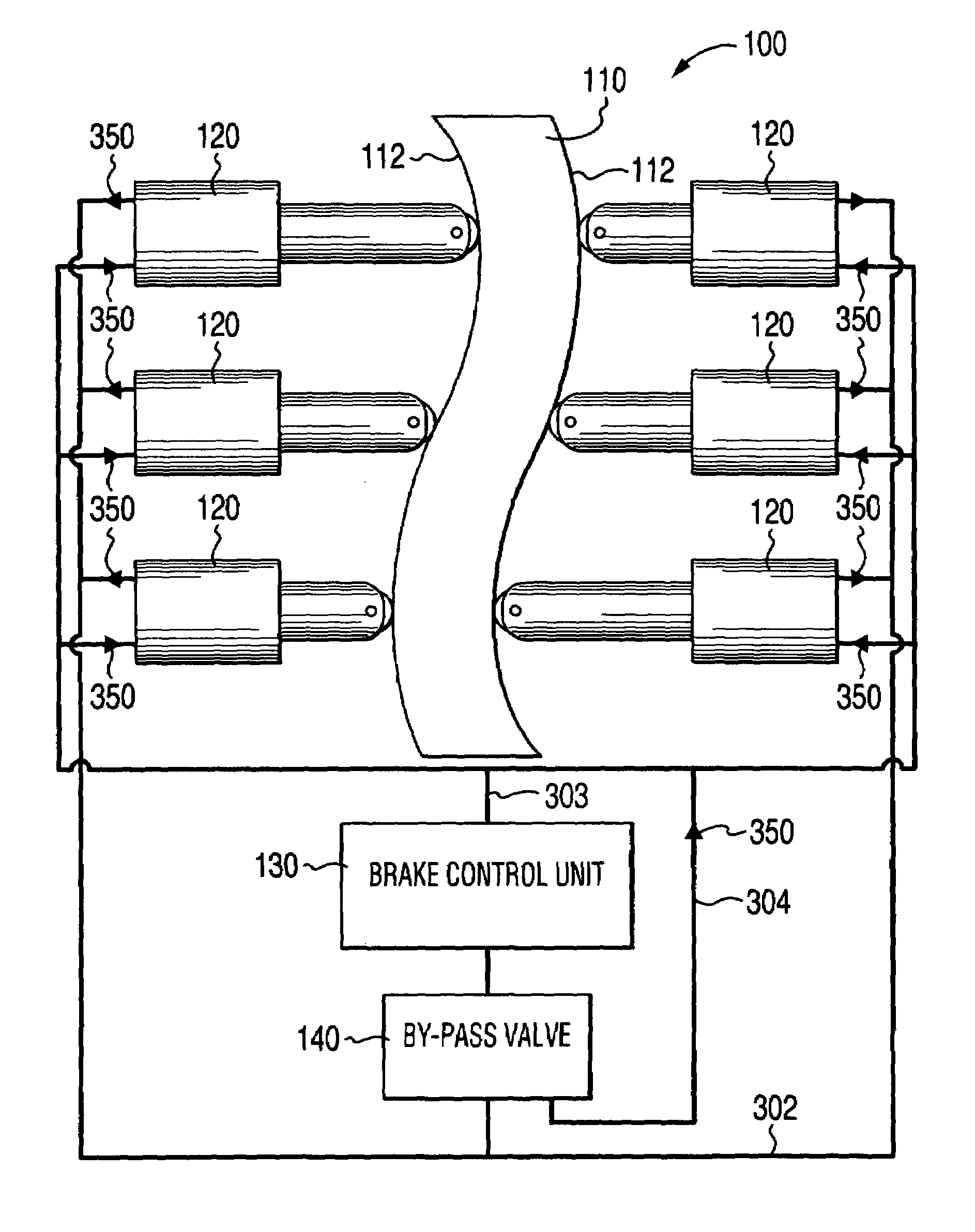
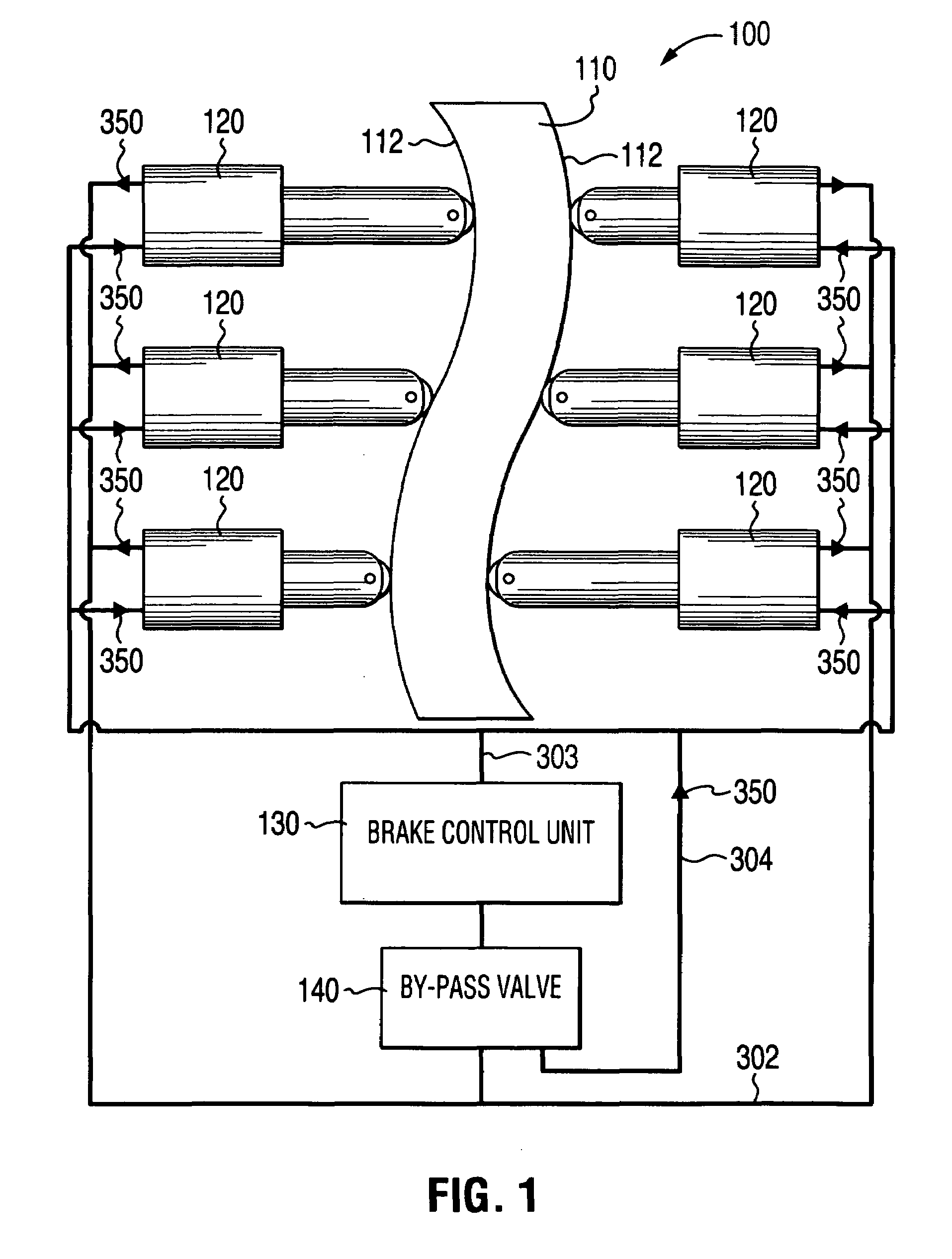
[0016]FIG. 1 is a schematic representation of an exemplary embodiment of a braking system 100 according to the present invention for use in, for example, a wheeled vehicle. The braking system 100 is comprised of an interface mechanism in the form of a rotor 110, a plurality of actuators 120, a brake control unit 130 and a by-pass valve 140. The rotor 110 can be connected to a vehicle wheel (not shown) so as to rotate when the wheel rotates. The braking system 100 has a brake-on and a brake-off mode of operation.

[0017]In the brake-on mode of operation, each of the plurality of actuators 120 engages the rotor 110 to impart a braking (decelerative) force to the rotor 110 and thereby to the wheel. In the brake-off mode of operation, none of the plurality of actuators 120 applies any substantial braking force to the rotor 110. The brake control unit 130 is operable between a brake-on position and a brake-off position that effect the brake-on and the brake-off modes of operation respectiv...


PUM


Abstract

A braking system comprised of a rotor, a plurality of actuators, a brake control unit and a by-pass valve. When in a brake-on mode of operation, the brake control unit effects braking by restricting the flow of a working fluid that is pumped in and out by each of the plurality of actuators as they engage the rotating rotor. The degree of restriction to the flow of the working fluid can be varied to adjust the amount of braking force applied. The brake system is self-energizing in that it is not reliant on a substantial external source to create the operating pressure necessary to effect braking. Operating the by-pass valve into a by-pass on position effectively negates the generation of braking forces normally resulting from operation into the brake-on mode of operation while still allowing the actuators to engage the rotor and working fluid to be circulated.

Description

FIELD OF INVENTION[0001]The present invention relates to the field of brake systems. In particular, to brake systems that do not require significant external energization in order to operate.BACKGROUND[0002]Braking systems such as those used to retard the motion of all manner of wheeled transportation vehicles come in many forms. The brake systems are most typically of a drum or disk configuration with a shoe or pad made of abrasive material acting on the drum or disk, respectively, to produce a friction derived braking force. Application of the shoe or pad is usually accomplished by the application of force, in the form of pressure, to press an abrasive face of the shoe or pad against the drum or disk.[0003]In early brake systems the force pressing on the shoe or pad was applied mechanically using mechanical advantage (leverage) to augment the brake force applied by the vehicle operator at the operator interface (usually a brake pedal). Later systems used a hydraulic circuit to con...

Claims


Application Information

Patent Timeline
Patent Type & Authority Patents(United States)
IPC IPC(8): B60T1/10B60T10/00B60T10/04B60T1/00B60T1/093
CPCB60T1/093B60T1/10B60T10/04
Inventor CANNATA, ANTONIO
Owner TONAND BRAKES
Why Eureka
Try Eureka